
herunterladen

Application Note Please read the Important Notice and Warnings at the end of this document <Revision 2.0>
www.infineon.com <2017-11-15>
AN2010-09_HYBRIDPACK-DSINFO
HybridPACK™ Automotive Power Modules
Explanation of Technical Information
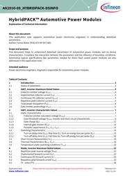
About this document
This application note supports automotive power electronics engineers in understanding datasheet
parameters.
Author: Tomas Reiter (IFAG ATV HP EDT MD).
Scope and purpose
This document helps to understand datasheet parameters of automotive power modules and its device
characteristics. It explains the interaction between the parameters and the influence of boundary conditions.
Automotive typical specifications like parameters needed for direct fluid cooled power modules are also
addressed in this application note.
Intended audience
Power electronics engineers. Engineers responsible for automotive power modules.
Table of Contents
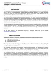
1 Introduction .................................................................................................................. 3
1.1 Status of datasheets ................................................................................................................................ 3
2 IGBT, Inverter Maximum Rated Values ............................................................................. 4
2.1 Collector-emitter voltage (V
CES
) ............................................................................................................... 4
2.2 Implemented collector current (I
CN
) ....................................................................................................... 4
2.3 Continuous DC collector current (I
Cnom
) .................................................................................................. 5
2.4 Repetitive peak collector current (I
CRM
) .................................................................................................. 5
2.5 Total power dissipation (P
tot
) .................................................................................................................. 6
2.6 Gate-emitter peakvoltage (V
GES
) .............................................................................................................. 6
3 IGBT, Inverter Characteristic Values ................................................................................ 7
3.1 Static Characteristics .............................................................................................................................. 7
3.1.1 Collector-emitter saturation voltage (V
CEsat
) ...................................................................................... 7
3.1.2 Gate threshold voltage (V
GEth
), transfer and short circuit characteristic .......................................... 9
3.1.3 Gate charge (Q
G
) ............................................................................................................................... 11
3.1.4 Internal gate resistor (R
Gint
) .............................................................................................................. 12
3.1.5 Parasitic capacitances (C
ies
, C
res
, C
oes
)............................................................................................... 13
3.2 Switching Characteristics ..................................................................................................................... 15
3.2.1 Turn-on delay time (t
d on
), Rise time (t
r
), Turn-on energy loss per pulse (E
on
) ................................ 15
3.2.2 Turn-off delay time (t
d off
), Fall time (t
f
), Turn-off energy loss per pulse (E
off
) ................................. 16
3.3 Short Circuit Characteristics (I
sc
) ........................................................................................................... 18
3.4 Thermal Characteristics (R
thJF
, Z
thJF
) ...................................................................................................... 19
3.5 Temperature under switching conditions (T
vj op
) .................................................................................. 22
4 Diode, Inverter Maximum Rated Values ........................................................................... 23
4.1 Repetitive peak reverse voltage (V
RRM
) .................................................................................................. 23
4.2 Implemented forward current (I
FN
) ....................................................................................................... 23
4.3 Continuous DC forward current (I
F
) ...................................................................................................... 23
4.4 Repetitive peak forward current (I
FRM
) .................................................................................................. 23
4.5 I²t - value (I²t) ......................................................................................................................................... 24