
herunterladen
Application Specification
AMPLIMITE* .050 Series Cable End
Insulation Displacement Connector (IDC)
114--40029
1 of 20
LOC B
E2011 T yco Electronics Corporation, a TE Connectivity Ltd. Company
All Rights Reserved
*Trademark
TE Connectivity, TE connectivity (logo), and TE (logo) are trademarks. Other logos, product and/or Company names may be trademarks of their respective owners.
TOOLING ASSISTANCE CENTER 1 --800--722--1111
PRODUCT INFORMATION 1--800--522--6752
This controlled document is subject to change.
For latest revision and Regional Customer Service,
visit our website at www.te.com
and Printed Circuit (PC) Board Connector
17 JAN 12 Rev J
All numerical values are in metric units [with U.S. customary units in brackets]. Dimensions are in millimeters [and
inches]. Unless otherwise specified, dimensions have a tolerance of +0.13 [+.005] and angles have a tolerance of +2_.
Figures and illustrations are for i dentification only and are not drawn to scale.
1. INTRODUCTION
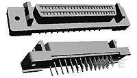
This specification covers the requirements for application of AMPLIMITE .050 Series cabl e end IDC and pc
board connector. The connectors offer high--density “D” mati ng (keystone configuration) interfaces avai lable in
plug and receptacles with 20 through 120 positions (sizes) having 1.27¢2.54 [.050¢.100] contact centerlines.
The connectors are available with a metal shel l over a plastic housing for electromagnetic interference
shiel ding (EMI) and electrostatic discharge (ESD) shielded applications.
The cable end connector contains insulation displacement contacts and is availabl e with pre--assembled or
unassembled termination covers. The cable end connector is available for free--hanging applications or
panel--mount applications.
Feed--through cable end connectors are also available and are covered in Application Specification 114--40049.
For free--hanging cable end connectors, a shielded metal backshell, available with a straight cable exit or
angled cable exit, must be used to provide cabl e strain relief and prevent movement of the terminated wires in
the insul ation displ acement contacts. The metal backshel l consists of two intermating halves and a serrated
strain--relief staple. The strain--relief staple is used to clamp the cable bundle to the lower half of the metal
backshell, which reduces stress on the termi nated wires. Strai ght cable exit and angled cable exit metal
backshells are available in kits that include latches. Latches lock wi th a mating connector that has either latch
blocks or latch block and rails. Straight cable exit metal backshells are available in kits that include jackscrews.
Jackscrews secure the cable end connector with a mati n g connector that has screwlocks.
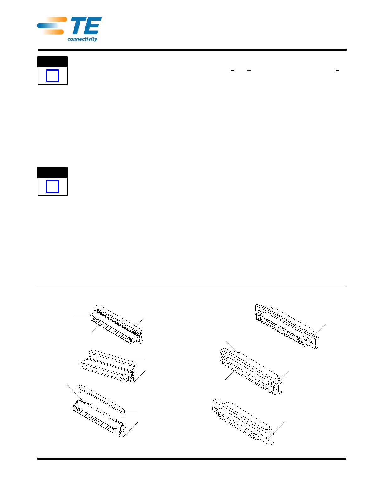
When corresponding with personnel , use the terminol ogy provided in thi s specification to facilitate your
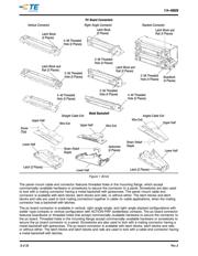
inquiries for information. Basic terms and features of this product are provided in Figure 1.
Figure 1 (Cont’d)
Optional
Latch Block
(2 Places)
Optional Latch Block
and Rail (2 Places)
Pre--Assembled
Termination Covers
Insulation
Displacement
Contacts
Free Hanging Panel Mount
Cable End Connectors
Unassembled
Termination Covers
Metal Shell
Threaded Hole for Mounting
Screw or Screwlock (2 Places)
Metal Shell
Plastic Housing
Unassembled
Termination Covers
Plastic Housing
NOTE
i
NOTE
i