

herunterladen
a
AN-535
APPLICATION NOTE
One Technology Way • P.O. Box 9106 • Norwood, MA 02062-9106 • 781/329-4700 • World Wide Web Site: http://www.analog.com
Digital Input/Output Subsystems
INTRODUCTION
The DB-16 and DB-24 are 16- and 24-channel digital I/O
subsystems providing a reliable, solid state, optically
isolated interface between data acquisition boards, such
as the Analog Devices’ RTI-800 series, or distributed I/O
signal conditioning subsystems such as the Analog
Devices’ Model 6B50, and discrete high level I/O.
The DB-16 is a manifold card that accepts up to 16
single-channel digital input and output modules. These
solid state relay modules can be mixed and matched to
provide an interface to ac inputs, ac outputs, dc inputs
and dc outputs. Each I/O module is individually con-
trolled or sensed by the digital I/O of the data acquisition
board or the 6B50 subsystem.
The DB-24 is a manifold card that can accept up to six
4-channel (quad) digital input and output modules.
These modules can be mixed and matched as well. Each
module handles four channels of identical levels, and
the state of each input or output can be observed via the
four LEDs on each module.
The DB-16 and DB-24 share the same pinout and 50-pin
card edge connector and can be used interchangeably.
However, only the 16 channels are addressable on the
DB-16. An external +5 V dc power supply at 300 mA
maximum is required for operation.
DB-16 Digital I/O Subsystem
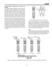
Use the DB-16 Digital I/O Backplane, shown in Figure 1,
and its associated ac and dc single-channel I/O modules
to measure and/or control high level ac and dc signals or
if isolation of the digital I/O is required.
Single-Channel Solid State Relays
The DB-16 supports the installation of up to 16 single-
channel, solid-state relay modules, which provide
2500 V peak of optical isolation. You should install the
modules in their appropriate positions in the backplane
and secure them with one screw each.
All output modules can switch up to three amps. AC out-
put modules provide zero voltage turn-on and have an
RC (resistor-capacitor) snubber network for increased
capability with inductive loads. AC and dc input mod-
ules are designed with filtering on the input and hyster-
esis for high noise rejection and transient-free “clean”
switching. They are designed so that high voltage tran-
sients on the input do not cause damage to the module.
Each module operates by negative true logic, in which a
low digital voltage turns on current to the module. Indi-
vidual LED status indicators monitor module activity
and light when the current is ACTIVE.
Each I/O module position on the DB-16 backplane has
a 5 amp, 250 V rms pico-fuse (Littelfuse
®
Part Number
251 005) protecting the module and wiring from short
circuits.
49
1
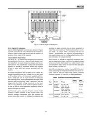
KEY
SLOT
0123456
7
8 9 10 11 12 13 14
15
BARRIER STRIP FOR
LOGIC SUPPLY INPUT
POWER BARRIER
STRIP
POWER LINE
FUSE, 5 AMP
PULL-UP RESISTOR
3.3kV
SIGNAL CARD EDGE
CONNECTOR
Figure 1. DB-16 Digital I/O Backplane
All trademarks are the property of their respective holders.
Verzeichnis