


herunterladen

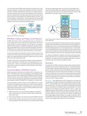
Figure 1. (a) BLDC block commutation control and (b) BLDC sine commutation control.
Gate
Drivers
Gate
Drivers
(a) (b)
Microcontroller
Microcontroller
Hall
Switch
Hall
Switch
Hall
Switch
VISIT ANALOG.COM
Vol 53 No 4, November 2019
Dual AMR Motor Position
Sensor for Safety
Critical Applications
Enda Nicholl , Strategic Marketing Manager
Abstract
This article provides insight into the trends in automotive electri-
fication as we move toward partial and full autonomous driving
and, in particular, the changes required to make electrical power
steering
(
EPS
)
and electrical braking systems meet the necessary
safety standards to ensure the safe and reliable control of driver-
less vehicles.
Analog Devices, Inc.
(
ADI
)
is a provider of magnetoresistive
(
MR
)
position sensor products and shunt-based current sense amplifier
products enabling high performance commutation and safe opera-
tion of brushless motors used in EPS and electrical braking systems.
Introduction
The increased emphasis to improve vehicle safety in recent years has
resulted in the welcome advancement and introduction of active advanced
driver assistance systems
(
ADASs
)
to complement the traditional passive
systems reliant on airbag deployment for driver and passenger safety.
These emerging systems are intended to initially aid—but longer term
replace—the driver’s vehicle maneuver decision making in safety critical
situations. These technology advancements are also leading the way to
the transition to semi- and fully autonomous driving. Replacing the driver’s
decision making with electronic control units
(
ECUs
)
and replacing the
steering and brake maneuvering of the vehicle with actuators is shifting
responsibility away from the driver to the sensors, the ECUs, and the elec-
trical actuators. This trend is leading to the development of more reliable,
intelligent, higher performance, and redundant electrical actuator solutions
that need to comply with the ISO 26262 functional safety standard. This
is a risk-based safety standard, where the risk of hazardous operational
situations is qualitatively assessed, and safety measures are designed into
the components and system to avoid or control systematic failures and to
detect or control random hardware failures or mitigate their effects. These
actuator systems generally use brushless dc
(
BLDC
)
motor drives, and as
these systems are safety critical, the designers must design the solution
hardware and software such that the system complies with the highest
automotive safety integrity level
(
ASIL
)
D.
BLDC Motor Commutation and Control
Brushless dc motors, as the name suggests, have no brush contacts, and
motor position sensors
(
MPSs
)
are needed to measure the relative position
between the stator and rotor to ensure the correct stator coil energizing
sequence. This is particularly critical at startup when there is no back EMF
available and it is impossible for the microcontroller to determine the rela-
tive rotor and stator positions.
Traditionally, block commutation
(
see Figure 1a
)
, which is comprised of
three Hall switches, has been used to indicate the rotor position in BLDC
motors. The demands to improve performance and, in particular, reduce
noise, vibration, and harshness
(
NVH
)
and improve running efficiency of
BLDC motor drives
(
including EPS systems
)
is resulting in a move away from
block commutation to sine commutation control. The Hall switches can be
replaced with an MR angle sensor positioned in front of a bipole magnet
mounted onto the end of the motor shaft
(
see Figure 1b
)
. It is also typical for
the MPS to be mounted onto the ECU assembly and for the ECU to be inte-
grated into the motor casing and positioned at the end of the motor shaft.