

herunterladen

Rev. 0 | Page 1 of 8
One Technology Way • P. O. Box 9106 • Norwood, MA 02062-9106, U.S.A. • Te l: 781.329.4700 • Fax: 781.461.3113 • www.analog.com
by David Brandon, David Crook, and Ken Gentile
AN-0996
APPLICATION NOTE
The Advantages of Using a Quadrature Digital Upconverter (QDUC) in
Point-to-Point Microwave Transmit Systems
INTRODUCTION
Direct conversion and super heterodyne transmitter architec-
tures are commonly used in wireless systems. This application
note briefly reviews the pros and cons of each approach (addi-
tional resources are listed in the References section) and also
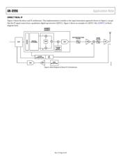
offers an architectural option (direct real IF) that is well suited
for IF generation in the indoor unit (IDU) section of a microwave
erter
power
local
I/Q)
he
inexpensive discrete inductors and capacitors. Care must be
uces modulation
e
d
ed
d
alog
k
errors due to temperature and supply voltage variations.
point-to-point radio.
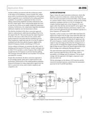
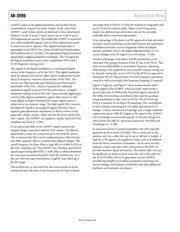
DIRECT CONVERSION
A direct conversion transmitter is shown in Figure 1. This
architecture is favored for its simplicity and low cost relative to
the super heterodyne approach. The key architectural blocks
include an AD9779 dual baseband digital-to-analog conv
(DAC), associated reconstruction filters, an AD8349 or
ADL537x analog quadrature modulator, band filter, and
amplifier (PA) circuitry. An RF PLL produces the
oscillator (LO) signal that drives the modulator.
The dual DAC outputs generate in-phase and quadrature (
components of a complex baseband signal resulting from
modulation mapping, pulse shaping, and upsampling (via
interpolation filters) to the DAC sample clock frequency. T
DAC reconstruction filters are usually implemented with
taken to avoid introducing any group delay variation between
the reconstruction filter because this introd
distortion resulting in EVM degradation.
The filtered baseband I/Q signals along with the LO signal driv
the corresponding I/Q and LO inputs of an analog quadrature
modulator. The quadrature modulator produces a modulate
RF waveform at a carrier frequency that is equal to the LO
frequency. This modulated output signal is band filtered (to
remove out-of-band spurs) and amplified by the PA circuitry.
A common problem associated with this approach is referr
to as LO leakage: the presence of the LO signal within the
modulated signal bandwidth. Since this distortion term is in-
band, it cannot be filtered out. The origin of this error is relate
to parasitic coupling as well as mismatches in the dc compo-
nents of the signals at the modulator inputs. This includes DAC
offsets as well as input offset voltages associated with the an
quadrature modulator. It is possible to cancel this effect by
applying a compensating offset signal from the DAC. For a
robust solution, however, this correction signal must trac
DAC
ADC
DAC
RECONSTRUCTION
FILTER
RECONSTRUCTION
FILTER
BAND
FILTER
AMP
VGA PA
RMS
DETECTOR
CLOCK
GENERATION
DIGITAL
FILTERING
DSP
0/90
Q
I
AD9779
A
D8349
ADL537x
07997-001
RF
PLL
LO
Figure 1. Block Diagram of Direct Conversion Tx Architecture