


herunterladen
AN-667
APPLICATION NOTE
One Technology Way • P.O. Box 9106 • Norwood, MA 02062-9106 • Tel: 781/329-4700 • Fax: 781/326-8703 • www.analog.com
We will use the programmable reset generator inputs
(supply fault detectors, or SFDs) of the ADM1060 to ensure
that the supplies are in tolerance. These can be assigned
as follows:
Table I. Supply Fault Detector Assignment
ADM1060 Minimum Threshold
Supply Input Pin Fault Type Voltage (V)
3.3 V VP1 Undervoltage 3.135
2.5 V VP2 Undervoltage 2.375
1.8 V VP3 Undervoltage 1.71
We will use the programmable driver outputs (PDOs) on
the ADM1060 to enable all of the supplies. These can be
assigned as follows:
Table II. Programmable Driver Output Assignment
Supply Driver Output Output Conguration
3.3 V PDO1 Charge Pump*
2.5 V PDO2 Logic
1.8 V PDO3 Logic
*PDO1 is congured as a charge pump output because it is required to
drive the gate of a FET.
With the resources of the ADM1060 assigned as outlined
above, the hardware can be congured as described
below.
Since PDO1 is to be used to turn on and off the 3.3 V
supply, we will use PLB1 to program the logic required to
control the 3.3 V supply. We will use Function A to control
the power-up and Function B to control the power-down.
Similarly, for programming PDO2 and PDO3, we will use
PLB2 and PLB3.
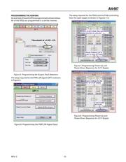
POWER-UP SEQUENCE
The following sequence occurs at power-up:
1. PWR_ON goes high.
2. 100 ms later, the 3.3 V supply to the rest of the board
is enabled when the FET is turned on.
3. The voltage on the source of the FET rises to a minimum
threshold level, for example, within 5% of nominal (i.e.,
3.13 V).
INTRODUCTION
The ADM1060 is a fully programmable supply sequencer
and supervisor. It can be used as a complete supply man-
agement solution in any system using multiple voltage
supplies. Such applications include line cards in telecom-
munications infrastructure equipment (central ofce, base
stations, etc.) and “blade” cards in servers.
One very powerful function of the ADM1060 is the ability
to sequence the turn-on of as many as seven supplies
in any order the designer requires. Furthermore, the
ADM1060 can be used to sequence the turn-off of the sup-
plies, in an order independent of the power-up sequence.
This application note describes how to easily program
this function using intuitive GUI based software avail-
able from Analog Devices. This note should be referred
to in conjunction with the ADM1060 data sheet and the
ADM1060 Evaluation Tools note.
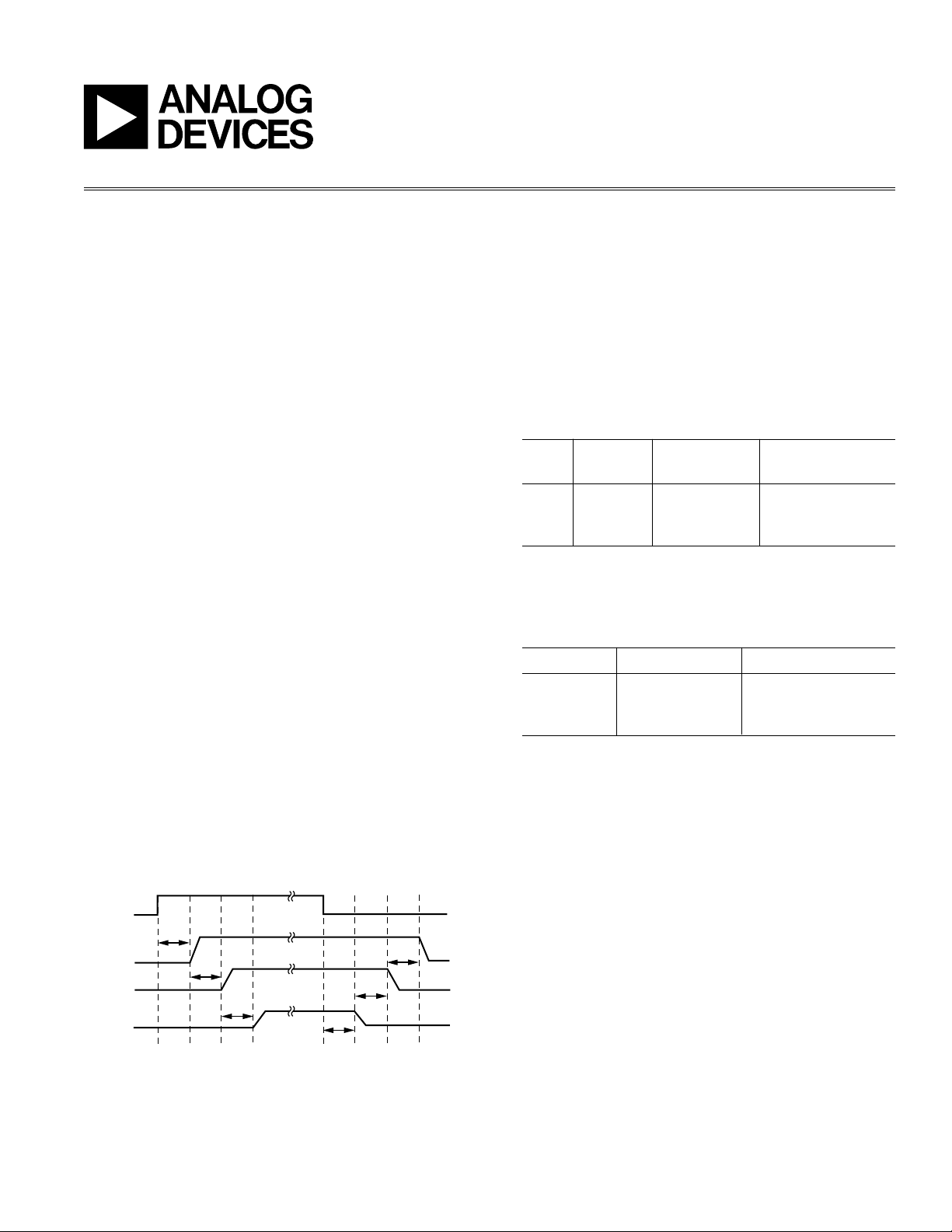
THREE-SUPPLY UP/DOWN SEQUENCE
Suppose the user wants to sequence three supplies
(3.3 V, 2.5 V, and 1.8 V) so that they turn on in order, starting
with the supply with the highest voltage and continuing
in descending order, with a 100 ms delay between each
supply. Some time later, they are to turn off in the reverse
order. The 3.3 V is always available on the board, while
the 2.5 V and 1.8 V are generated by LDOs on the board,
using the 3.3 V supply as a voltage input.
The sequence described is shown in the timing diagram
below.
Figure 1. Power-Up and Power-Down Sequence
Up/Down Sequence of Supplies Using the ADM1060
By Peter Canty
REV. 0