
herunterladen

®
©
2000 Burr-Brown Corporation AB-158 Printed in U.S.A. April, 2000
TOUCH SCREEN CONTROLLER TIPS
By Skip Osgood, CK Ong, and Rick Downs
Burr-Brown makes a number of specialized analog-to-digi-
tal converters for touch screen applications. The ADS7843,
ADS7845, and the new ADS7846 converters all are de-
signed for specific touch screen applications. Applications
using these devices can benefit greatly from the tips pre-
sented in this application bulletin. Most of the examples
discuss the ADS7843, but the techniques shown are appli-
cable to all of the devices.
We begin by looking at the theory of operation of a resistive
touch screen, and using these specialized A/D converters
with such a screen. Techniques are presented for improving
accuracy and minimizing errors; the operation of the pen
interrupt line (PENIRQ) is explored, ESD protection meth-
ods for the converters, and issues surrounding interfacing
these converters to popular microprocessors are discussed.
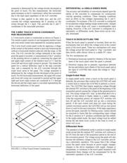
RESISTIVE TOUCH SCREENS
A resistive touch screen works by applying a voltage across
a resistor network and measuring the change in resistance at
a given point on the matrix where a screen is touched by an
input stylus, pen, or finger. The change in the resistance ratio
marks the location on the touch screen.
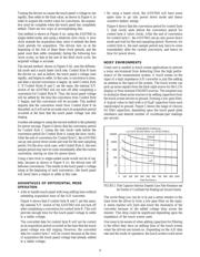
The two most popular resistive architectures use 4-wire or
5-wire configurations (as shown in Figure 1). The circuits
determine location in two coordinate pair dimensions, al-
though a third dimension can be added for measuring pres-
sure in 4-wire configurations.
THE 4-WIRE TOUCH SCREEN COORDINATE
PAIR MEASUREMENT
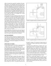
A 4-wire touch screen is constructed as shown in Figure 2.
It consists of two transparent resistive layers.
The 4-wire touch screen panel works by applying a voltage
across the vertical or horizontal resistive network. The A/D
converts the voltage measured at the point the panel is
touched. A measurement of the Y position of the pointing
device is made by connecting the X+ input to a data
converter chip, turning on the Y+ and Y– drivers, and
digitizing the voltage seen at the X+ input. The voltage
FIGURE 1. 4-Wire and 5-Wire Touch Screen Circuits.
Four-Wire Five-Wire
Conductive Bar
Insulating
Material
(Glass)
Silver
Ink
Transparent
Conductor (ITO)
Bottom Side
Transparent
Conductor (ITO)
Top Side
X+
X–
Y+
Y–
ITO = Indium Tin Oxide
FIGURE 2. 4-Wire Touch Screen Construction.
SBAA036
Verzeichnis
- ・ Blockdiagramm on Seite 5
- ・ Anwendungsbereich on Seite 1