
herunterladen
AL8821
Document number: DS37671 Rev. 1 - 2
1 of 14
www.diodes.com
January 2015
© Diodes Incorporated
AL8821
NEW PROD UCT
40V, 2A BOOST LED DRIVER
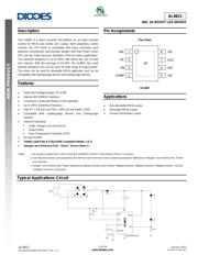
Description
The AL8821 is a boost converter that delivers an accurate constant
current for MR16 and similar LED Lamps. With proprietary control
scheme, the LED driver is compatible with many commonly used
electronic transformers and provides designs with High Power Factor
(PF) and low Total Harmonic Distortion (THD) for these applications.
The operation frequency is up to 1MHz that allows the use of small
size inductor. With the package of SO-8EP, the AL8821 has small
thermal resistance and can be used for wide range of output power.
The driver can be used for dimmable MR16 application and can be
compatible with leading-edge dimmer and trailing-edge dimmer.
Features
Wide Input Voltage Range: 5V to 36V
Internal 40V NDMOS Switches
Continuous Conduction Mode (CCM) Operation
Up to 1MHz Switching Frequency
High PF > 0.9 and Low THD < 30% and low Ripple < 20%
Compatible With Leading-edge Dimmer And Trailing-edge
Dimmer
Internal Protections
Under Voltage Lock Out (UVLO)
Output Open
Over Temperature Protection (OTP)
Pb-free SO-8EP
Totally Lead-Free & Fully RoHS Compliant (Notes 1 & 2)
Halogen and Antimony Free. “Green” Device (Note 3)
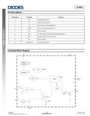
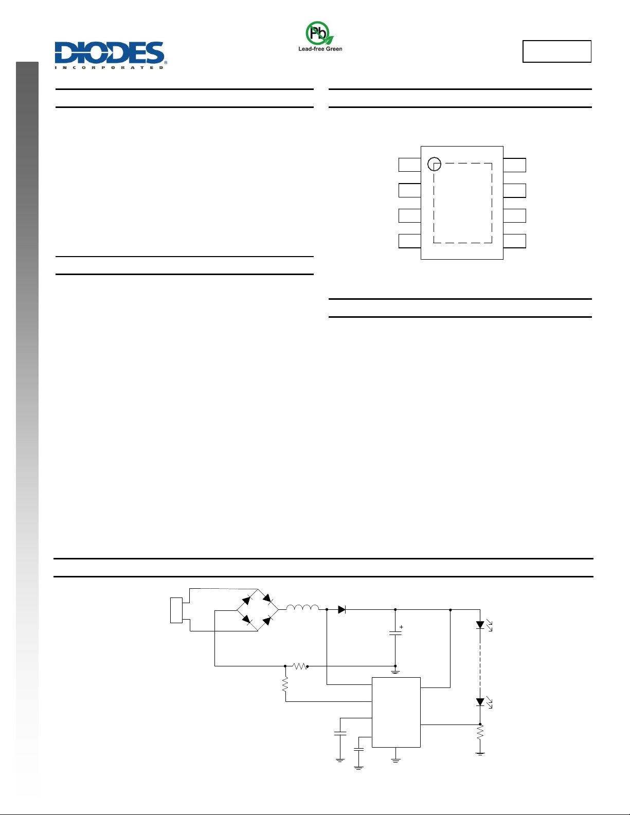
Pin Assignments
(Top View)
1
2
3
4
8
7
6
5
SW
CS
FB
COMP
NC
VCC
VIN
NC
EP
SO-8EP
Applications
Non-dimmable MR16 Lamps
Dimmable MR16 Lamps
General Illumination Lamps
Notes: 1. No purposely added lead. Fully EU Directive 2002/95/EC (RoHS) & 2011/65/EU (RoHS 2) compliant.
2. See http://www.diodes.com/quality/lead_free.html for more information about Diodes Incorporated’s definitions of Halogen- and Antimony-free, "Green"
and Lead-free.
3. Halogen- and Antimony-free "Green” products are defined as those which contain <900ppm bromine, <900ppm chlorine (<1500ppm total Br + Cl) and
<1000ppm antimony compounds.
Typical Applications Circuit
D2
D1
D3
D4
D5
R
SET
R
HYS
C
O
C3
SW
CS
VCC
COMP
VIN
(Exposed Pad)
L
C4
Vac
AL8821
FB
R
FB
Verzeichnis
- ・ Konfiguration des Pinbelegungsdiagramms on Seite 1 Seite 2
- ・ Abmessungen des Paketumrisses on Seite 12
- ・ Paket-Footprint-Pad-Layout on Seite 13
- ・ Teilenummerierungssystem on Seite 11
- ・ Markierungsinformationen on Seite 11
- ・ Blockdiagramm on Seite 2
- ・ Typisches Anwendungsschaltbild on Seite 1 Seite 7
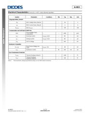
- ・ Technische Daten on Seite 3
- ・ Anwendungsbereich on Seite 1
- ・ Elektrische Spezifikation on Seite 3 Seite 4 Seite 5 Seite 6