

herunterladen

© Semiconductor Components Industries, LLC, 2009
August, 2009 − Rev. 3
1 Publication Order Number:
AND8411/D
AND8411/D
AMIS-30600 LIN Transceiver
Low Power Consumption
Introduction
This document describes how the AMIS−30600 LIN
transceiver can be used in low power environments.
Questions
How can I consume less power when the AMIS−30600 is
disabled (V
EN
= 0 V) and what will be the effect on the
TxD−, RxD−, INH−, and EN−pin when data is transmitted
over the LIN−bus?
Conclusion
Although the AMIS−30600 offers a sleep mode, it is
possible that the power consumption is still too high in some
applications. To reduce power consumption, V
CC
, V
bat
and
the LIN pullup resistor can be disconnected without any
unwanted effects on the TxD−, RxD−, EN−, and INH−pin
1
.
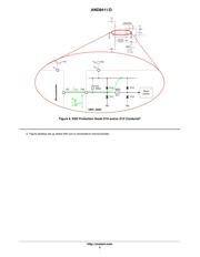
In the Conclusion and Advised Application Schematic
Section, an advised application schematic is provided to
reduce the AMIS−30600 supply current I
CC
and total battery
current consumption I
bat
to 0 A (microcontroller ignored
and ideal 5 V voltage regulator(s) assumed). In this way the
AMIS−30600 power consumption will be very low.
General
The single−wire transceiver AMIS−30600 is a monolithic
integrated circuit in a SOIC−8 package. It works as an
interface between the protocol controller and the physical
bus.
The AMIS−30600 is especially suitable to drive the bus
line in LIN systems in automotive and industrial
applications. Further it can be used in standard ISO9141
systems.
In order to reduce the current consumption the
AMIS−30600 offers a sleep mode. A wakeup caused by a
message on the bus pulls the INH−output high until the
device is switched to normal operation mode.
For more info about the AMIS−30600 LIN transceiver I
refer to the AMIS−30600 datasheet (www.onsemi.com).
Test Setup
To consume less power when the AMIS−30600 is in sleep
mode
2
, three possible setups will be examined.
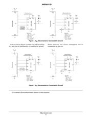
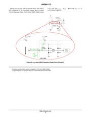
In the first setup, V
BB
will be disconnected or connected
to ground
3
(Figure 1: V
BB
Disconnected or Connected to
Ground). The behavior of the TxD−, RxD−, INH−, and
EN−pin will be examined when V
LIN
is between −40 V and
+40 V (−40 V < V
LIN
< +40 V) as also the current in these
pins will be measured. Additional, the current consumption
of the V
CC
−pin (AMIS−30600) and the battery current
consumption (I
bat
) will be measured.
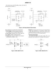
This test will be done with the INH−pin connected to an
I/O−pin of the microcontroller (by using a 12 V−to−5 V
converter) and with the INH−pin pulled to ground (with a
22k resistor).
1. AMIS−30600 is designed for V
BB
w V
CC
and the measurements are only done on one sample. Because of this,
ON Semiconductor cannot be held responsible if results (given in this document or measured yourself) are different than the data
sheet parameters or if there is a LIN Physical Spec violation when operating outside the normal supply range (+4.75 V < V
CC
<
+5.25 V and +7.3 V < V
BB
< +18 V).
2. A wakeup caused by a message on the communication bus automatically puts AMIS−30600 in stand−by mode and switches the
INH−pin to high output.
3. Connected to ground without resistor, capacitor or other component.
http://onsemi.com
APPLICATION NOTE
Verzeichnis