
herunterladen

Maxim > Design Support > Technical Documents > Application Notes > Power-Supply Circuits > APP 4324
Maxim > Design Support > Technical Documents > Application Notes > Temperature Sensors and Thermal Management > APP 4324
Keywords: LUT, look up table, temperature indexed, regulator, compensation, DS1859, potentiometer
APPLICATION NOTE 4324
Variable Resistor and Temperature-Indexed Lookup
Table (LUT) Compensate for Regulator Output
By: Jason Andrews
Jul 16, 2010
Abstract:
This application
note shows how a variable resistor controlled by an integrated, programmable,
temperature-indexed lookup table (LUT) is used to offset the temperature drift of regulators. In this application
the variable resistor changes value every 2°C based on the LUT. The variable resistor thus effectively nulls
any temperature changes (-40°C to +85°C) in a voltage regulator's output, and improves critical system
parameters. The DS1859 dual variable resistor serves as the example device.
A similar version of this article appeared in the July 9, 2009 issue of EDN magazine.
Introduction
A regulator provides a continuous, stable voltage to components downstream. Some applications tolerate
relatively large supply-voltage swings. Other applications are much more unforgiving of voltage fluctuations;
these precision circuits require the voltage regulation to be constant.
This article contrasts the results produced by a voltage regulator in a standard configuration with the results
from the same voltage regulator paired with the DS1859 dual, temperature-controlled resistors. The DS1859
compensates for temperature with one of its variable resistors and temperature-controlled lookup tables
(LUTs). The DS1859 thus clearly illustrates how a temperature-indexed LUT can improve critical system
parameters. Simpler devices, such as the DS1847 dual temperature-controller NV variable resistor, also
feature temperature-indexed LUTs and would work just as well. Furthermore, the DS1859 and DS1847 provide
closed-loop control without the need for a microcontroller.
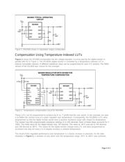
Uncompensated Voltage Regulation
A typical regulator circuit consists of the regulating element, a feedback resistor-divider, and capacitors to
provide some filtering and load regulation for transient or switching load conditions. The feedback resistor
network sets the regulator's output voltage, based on the ratio of the two resistors. In this article, the regulator
chosen was the MAX604, which can regulate at a preset 3.3V or any user-adjustable output within its
operating range. The MAX604 uses the voltage at the divider to determine its output voltage by feeding the
divided voltage into its SET input. As with most regulator circuits, there is a slight variation in output voltage
due to temperature. On the MAX604 this variation ranges from 97.6% to 101.5% of the nominal output voltage.
Data taken from the circuit shown in Figure 1 verifies this. At -45°C, the output is at 98% of the nominal
voltage reading; the output is 101% of nominal at +85°C. These are quite respectable numbers, but let's
investigate what can be done to improve these values even more.
Page 1 of 3