
herunterladen

Maxim > Design Support > Technical Documents > Application Notes > 1-Wire
®
Devices > APP 27
Maxim > Design Support > Technical Documents > Application Notes > Battery Management > APP 27
Maxim > Design Support > Technical Documents > Application Notes > iButton
®
> APP 27
Keywords: 1-Wire cyclic redundancy check (CRC), iButton CRC, ROM ID
APPLICATION NOTE 27
Understanding and Using Cyclic Redundancy
Checks with Maxim 1-Wire and iButton Products
Mar 29, 2001
Abstract: All 1-Wire
®
devices, including iButton
®
devices, contain an 8-byte unique registration number
in read-only memory (ROM). This registration number is used as a unique network address on a 1-Wire
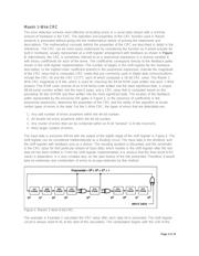
bus. To ensure data communication integrity, one byte of each registration number is a 1-Wire CRC
byte. This application note explains how to calculate this 8-bit 1-Wire CRC. It also goes on to explain the
16-bit CRC that is used to verify records saved in the memory of the devices. Both the 1-Wire CRC and
the CRC-16 are generated in hardware of select 1-Wire devices to validate data.
Introduction
The Maxim iButton products are a family of devices that all communicate over a single wire following a
specific command sequence referred to as the 1-Wire Protocol. A key feature of each device is a unique
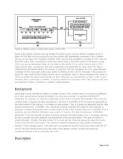
8-byte ROM code written into each part at the time of manufacture. The components of this 8-byte code
can be seen in Figure 1. The least significant byte contains a family code that identifies the type of
iButton product. For example, the DS1990A has a family code of 01 hex and the DS1922L has a family
code of 41 hex. Since multiple devices of the same or different family types can reside on the same 1-
Wire bus simultaneously, it is important for the host to determine how to properly access each of the
devices that it locates on the 1-Wire bus. The family code provides this information. The next 6 bytes
contain a unique serial number that allows multiple devices within the same family code to be
distinguished from each other. This unique serial number can be thought of as an "address" for each
device on the 1-Wire bus. The entire collection of devices, plus the host, form a type of miniature local
area network, or MicroLAN; they all communicate over the single common wire. The most significant
byte in the ROM code of each device contains a cyclic redundancy check (CRC) value based on the
previous 7 bytes of data for that part. When the host system begins communication with a device, the 8-
byte ROM is read, LSB first. If the CRC that is calculated by the host agrees with the CRC contained in
byte 7 of ROM data, the communication can be considered valid. If this is not the case, an error has
occurred and the ROM code should be read again.
Page 1 of 18