
herunterladen
Maxim > Design Support > Technical Documents > Application Notes > 1-Wire
®
Devices > APP 5507
Maxim > Design Support > Technical Documents > Application Notes > iButton
®
> APP 5507
Keywords: 1-Wire, bus master, VHDL, verilog, ASIC, FPGA
APPLICATION NOTE 5507
Understanding the DS1WM Synthesizable 1-Wire Bus
Master
By: Bernhard Linke, Principal Member Technical Staff
Oct 17, 2012
Abstract: Communication with 1-Wire
®
slave devices requires a 1-Wire master. There are numerous ways to build a 1-
Wire master (see reference design 4206, "Choosing the Right 1-Wire Master for Embedded Applications"). This
document describes the DS1WM, a synthesizable 1-Wire master that can be implemented in an application-specific
integrated circuit (ASIC) or field-programmable gate array (FPGA). The free DS1WM IP is available by request at
https://support.maximintegrated.com/1-Wire.
Introduction
With the growing popularity and diversity of 1-Wire devices, more engineers are facing the task of how to integrate a 1-
Wire master into their systems. Reference design 4206, "Choosing the Right 1-Wire Master for Embedded
Applications," describes various options. This document focuses on the DS1WM synthesizable 1-Wire bus master that
can be implemented as a function block of an application-specific integrated circuit (ASIC) or field-programmable gate
array (FPGA). The DS1WM core uses little chip area (~3470 gates plus two bond pads). It also generates the entire 1-
Wire timing by hardware, reducing the initial software development time and cost. Thus the entire application software
can be written in high-level language. Besides the 1-Wire communication signal DQ, the DS1WM also provides a
control signal STPZ, which assists in meeting the power requirements of certain 1-Wire slaves and allows for large
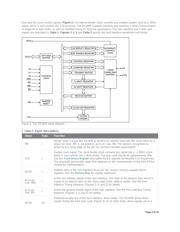
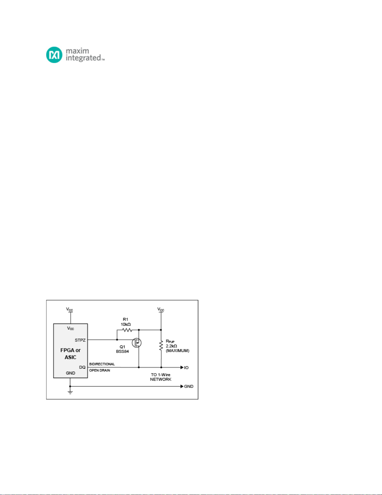
networks with many slaves or extensive cabling. Figure 1 shows the typical DS1WM application circuit. The DS1WM is
available for free in both Verilog and VHDL formats.
Figure 1. The DS1WM typical application circuit.
Description
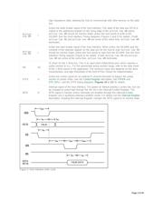
Similar to a memory device, the DS1WM connects to the user's system through an 8-bit data bus, using 3 address
Page 1 of 25
Verzeichnis