

herunterladen

Maxim > Design Support > Technical Documents > Application Notes > T/E Carrier and Packetized > APP 3422
Keywords: hardware mode, hardware
APPLICATION NOTE 3422
DS26502 Hardware Mode
Dec 23, 2004
Abstract:
The DS26502
data sheet contains all the information required to implement the DS26502 in a wide
variety of applications. The data sheet was written with the software-mode user in mind. It therefore contains
information required to set up the DS26502 using control registers to enable functionality that is not available
when using hardware mode.
This application note provides a focused view of the DS26502 functionality in hardware mode by excluding the
information in the data sheet that is only applicable when using software mode.
Introduction
There are two major modes of operation for the DS26502: software and hardware mode. The "mode" refers to
the method used to control the device's functionality. Applications implementing software mode use a
microcontroller's serial or parallel bus to communicate to the control registers contained in the DS26502. In
hardware mode, the functions of the serial/parallel communication bus pins are reassigned so that the logic
state of the pins provides direct control of the DS26502's internal functionality.
When Should Hardware Mode Be Used?
The advantage of using the DS26502 in hardware mode is that no microcontroller is required to control the
functionality.
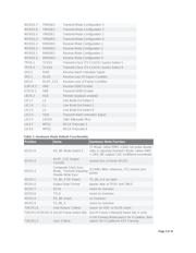
Each application has specific requirements that determine whether or not hardware mode may be used. The
designer's primary consideration is to determine whether any of the features available only in software mode
are required in the application. Table 1 lists all the software mode features not available in hardware mode.
The register bit position and the name are provided to easy reference to the complete functionality description in
the DS26502 data sheet.
Hardware Mode Implementation
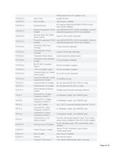
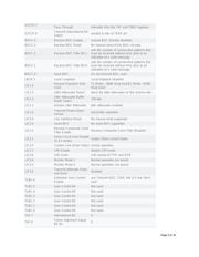
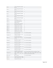
The DS26502 functionality is controlled by external pins in hardware mode. Table 2 is a reference for the
functionality of the software-mode bit positions and the corresponding pin used in hardware mode to control the
DS26502.
While some software-controllable features are totally eliminated in hardware mode, other features are present
but the functionality cannot be changed. The functionality of the unchangeable features, provided in Table 3,
was carefully chosen to perform as expected in normal applications using hardware mode. A complete
description of the hardware mode functionality for each pin is provided in Table 4. Figures 1 through Figure 4
are block diagrams of DS26502 functionality in hardware mode. The diagrams are similar to the software-mode
counterparts in the data sheet. In contrast to the block diagrams provided in the data sheet, the external pins of
the DS26502 in the figures here replace references to the control registers. Functionality for software-mode
only has also been removed.
Page 1 of 16
Verzeichnis