


herunterladen
October 2012 Doc ID 022923 Rev 1 1/14
AN4076
Application note
Two or three shunt resistor based current sensing circuit design in
3-phase inverters
By Stello Matteo Billè
Introduction
The ever increasing market demand for energy efficient systems - from motor vehicles to
home appliances, robotics to medical equipment, etc. - is pushing toward the adoption of
more and more efficient electric motors (e.g. 3-phase synchronous motors) and drives. The
field oriented control (FOC) scheme meets this demand while allowing, at the same time,
the achievement of a better regulation of electric motor torque and speed together with a
higher efficiency compared with many other solutions available on the market today.
This leads firstly to energy savings but at the same time to better performing systems: more
silent dishwashers and washing machines, better temperature regulation in air conditioned
environments or in refrigerators, higher autonomy in electric vehicles and much more. As
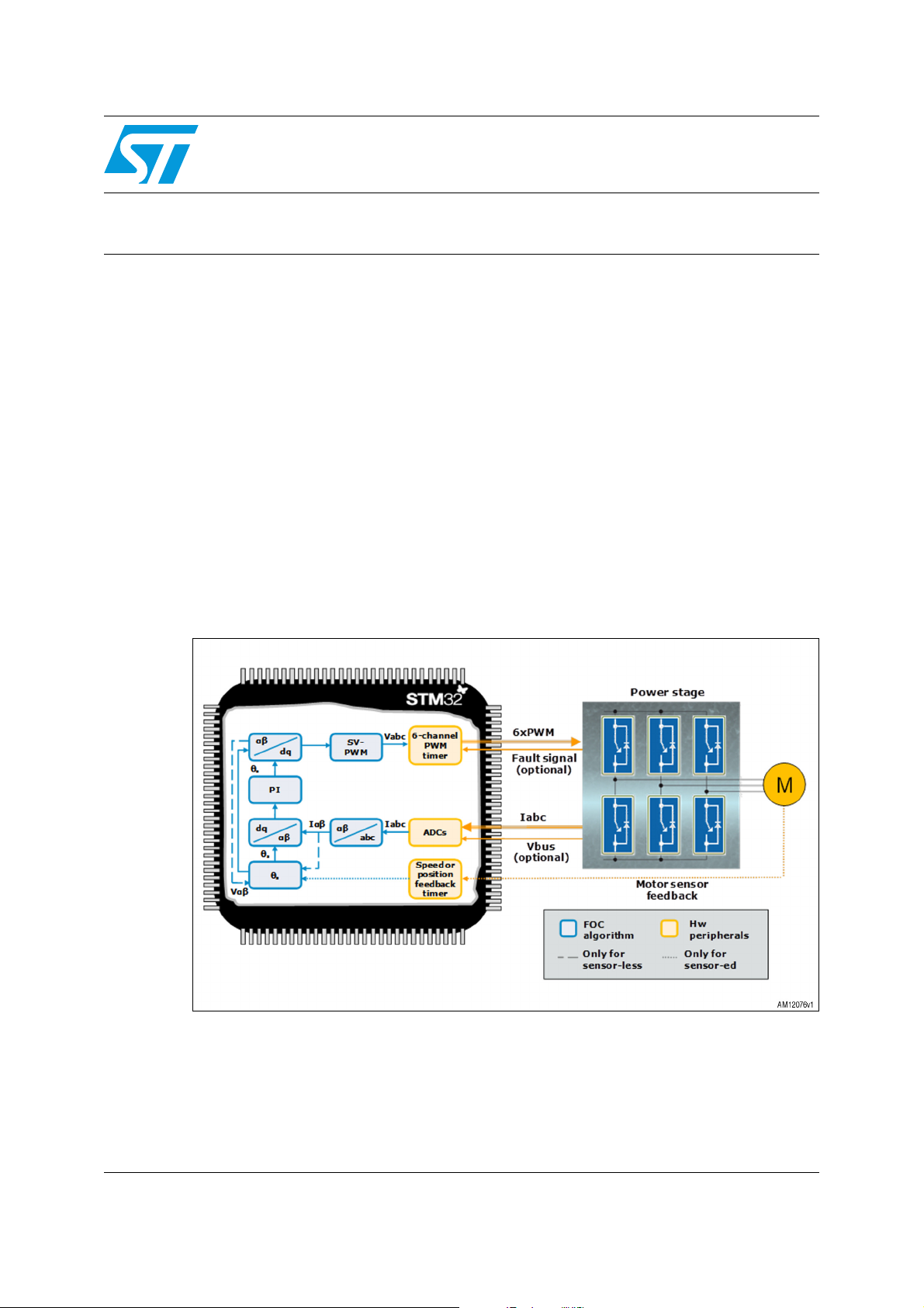
shown in Figure 1, the FOC scheme requires a knowledge of the controlled 3-phase motor
current; very often (for sensorless implementations) this is the only direct feedback between
the control unit and the electric motor. A precise and accurate motor current measurement is
therefore essential for the purpose of achieving satisfactory drive performance and, on the
contrary, an untailored sensing circuit may prevent the systems from even running.
Figure 1. Field oriented control scheme
Several hardware topologies can be used to measure motor currents; the aim of this
document is to provide designers with some useful tips for the design of the motor current
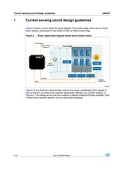
sensing circuit in a case where two (or three) shunt resistors, placed on the bottom of two
(or three) inverter legs, are used.
www.st.com
Verzeichnis