
herunterladen
Application Report
SNVA722B–September 2014–Revised February 2015
Inverting Applications Made SIMPLE with LM4600x and
LM4360x
AnstonLobo
ABSTRACT
We often require power sources with negative output voltages. There are many different ways to produce
a negative output voltage from a positive input voltage. One option is a polarity-inverting buck-boost
converter. The advantages of this topology are that it requires low component count and that it can be
built with standard high-side regulator ICs such as those intended for buck regulators. The LM4360x and
LM4600x synchronous family of SIMPLE SWITCHER
®
converters can be used in an inverting buck-boost
topology to provide a regulated negative output voltage rail in the system.
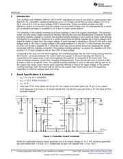
This user guide will demonstrate the use of LM46002 in an inverting buck-boost application. The design
accepts an input voltage of 15 V to 45 V and can provide an output voltage of -15 V capable of supplying
a range of output current to the load up to 1 A.
Contents
1 Introduction ................................................................................................................... 2
2 Board Specifications & Schematics ....................................................................................... 2
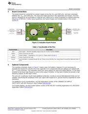
3 Board Connections .......................................................................................................... 3
4 Optional Components ....................................................................................................... 3
5 Design Parameters .......................................................................................................... 4
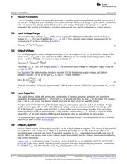
5.1 Input Voltage Range ............................................................................................... 4
5.2 Output Voltage ...................................................................................................... 4
5.3 Input Capacitor ..................................................................................................... 4
5.4 Output Capacitor.................................................................................................... 4
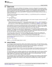
5.5 Output Current ...................................................................................................... 5
5.6 Inductor Selection................................................................................................... 5
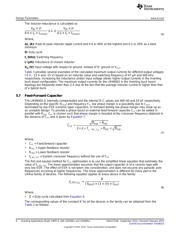
5.7 Feed-Forward Capacitor........................................................................................... 6
6 Bill of Materials............................................................................................................... 8
7 Performance Characteristics ............................................................................................... 9
8 PCB Layout Diagrams..................................................................................................... 13
9 Thermal Performance...................................................................................................... 17
List of Tables
1 Functionality of the Pins .................................................................................................... 3
2 Device Specific Constant Values .......................................................................................... 7
3 Calculated Output Current Range and Component Values for Different V
OUT
's based on LM46002 ............. 7
4 Evaluation Board Bill of Materials, V
IN
= 15 V to 45 V, V
OUT
= -15 V .................................................. 8
1
SNVA722B–September 2014–Revised February 2015 Inverting Applications Made SIMPLE with LM4360x and LM4600x
Submit Documentation Feedback
Copyright © 2014–2015, Texas Instruments Incorporated
Verzeichnis