
herunterladen

Application Report
SNVA674C–August 2012–Revised December 2014
AN-2292 Designing an Isolated Buck (Fly-Buck) Converter
VijayChoudhary
ABSTRACT
In many applications, one or more low-cost, simple to use, isolated power supplies working from input
voltages up to 100 V are needed. Traditional solutions use flyback converters to generate this bias supply.
Flyback designs typically utilize asymmetric transformers turns ratios for primary and secondary power
windings, with an optocoupler and reference, or an auxiliary winding for feedback regulation. Additionally,
flyback converters need an elaborate compensation design for stability. This results in a tedious design
process, bulky solution, with a higher component count and cost.
An isolated buck converter (Fly-Buck) uses a synchronous buck converter with coupled inductor windings
to create isolated outputs. Isolated converters utilizing Fly-Buck topology use a smaller transformer for an
equivalent power transfer as the transformer primary and secondary turns ratios are better matched.
There is no need for an optocoupler or auxiliary winding as the secondary output closely tracks the
primary output voltage, resulting in smaller solution size and cost.
This article presents the basic operating principle of an isolated buck converter. The operating current and
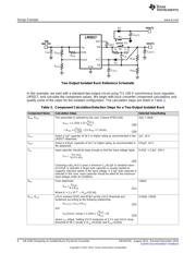
voltage waveforms are explained and design equations are derived. The design example shows a step-by-
step procedure for designing a practical two-output 3 W isolated buck converter.
Contents
1 Fly-Buck Converter .......................................................................................................... 1
2 Maximum Output Current Equations...................................................................................... 4
3 Design Example.............................................................................................................. 5
4 Conclusions................................................................................................................. 10
5 References.................................................................................................................. 10
List of Figures
1 Complete Schematic for an LM5017–Based Isolated Converter...................................................... 9
2 Efficiency at 750 kHz, V
OUT1
= 10 V........................................................................................ 9
3 Steady State Waveform (V
IN
= 48 V, I
OUT1
= 100 mA, I
OUT2
= 200 mA) ................................................ 9
4 Step Load Response (V
IN
= 48 V, I
OUT1
= 0, Step Load on I
OUT2
= 100 mA to 200 mA). ............................ 9
List of Tables
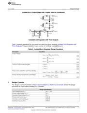
1 Isolated Buck Regulator Design Equations .............................................................................. 5
2 Component Calculation/Selection Steps for a Two-Output Isolated Buck ........................................... 6
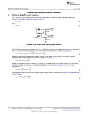
1 Fly-Buck Converter
An isolated buck converter, also known as Fly-Buck converter, is created by replacing the output filter
inductor (L1) in a synchronous buck converter with a coupled inductor (X1) or flyback-type transformer,
and rectifying the secondary winding voltage using a diode (D1) and a capacitor (C
OUT2
). The topology can
be extended to any number of isolated secondary outputs. It also can be used to generate one or more
inverting outputs.
All trademarks are the property of their respective owners.
1
SNVA674C–August 2012–Revised December 2014 AN-2292 Designing an Isolated Buck (Fly-Buck) Converter
Submit Documentation Feedback
Copyright © 2012–2014, Texas Instruments Incorporated
Verzeichnis
- ・ Blockdiagramm on Seite 5 Seite 6 Seite 9
- ・ Technische Daten on Seite 5
- ・ Anwendungsbereich on Seite 12