

herunterladen
Keywords: SAR, ADC, clock mode, optimal clock mode, trigger, acquisition, sampling, averaging, scan,
channels, conversion, SPI
APPLICATION NOTE 5966
CHOOSING THE OPTIMAL CLOCK MODE FOR
MAX116XX, MAX123X, AND MAX103X SAR
ADCS
By: Mohamed Ismail
Abstract: The MAX116xx, MAX103x, and MAX123x families of low-power, multichannel, 300ksps SAR
ADCs have configurable clock modes that enable flexibility when interfacing with a SPI master. This
application note discusses the advantages of each clock mode and provides timing examples for each
mode.
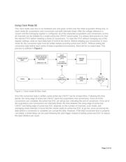
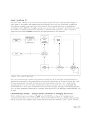
Choosing the Right Clock Mode for an Application
The MAX116xx, MAX103x, and MAX123x families of low-power, multichannel, 300ksps SAR ADCs have
configurable clock modes that enable flexibility when interfacing with a SPI master. The four different clock
modes allow the system designer to configure the throughput, pin count, and sample trigger. For designs
with limited hardware pins available, only four lines are required to operate these ADCs in clock modes 10
and 11. For highest throughput, clock mode 11 can be used to clock the conversion as data is
simultaneously read out. If precise control over the sampling instant is required, clock mode 01 provides the
system designer the ability to exactly trigger each acquisition externally. For systems with additional
hardware resources, clock modes 00, 01, and 10 provide a hardware indicator, active-low EOC, to signal
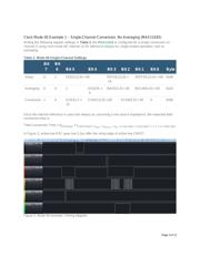
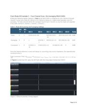
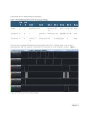
the end of conversion. A summary of the tradeoffs of using each clock mode is shown in Table 1.
Table 1. Summary of Clock Mode Differences
Pin
Count
Acquisition
Timing
Acquisition
Trigger Averaging Throughput
Mode
00
5 or 6 pins 1st Acquisition Only Active-low CNVST Yes Medium
Mode
01
5 or 6 pins Every Acquisition Active-low CNVST Yes Low
Mode
10
4 or 5 pins 1st Acquisition Only Active-low CS Yes Medium
Mode
11
4 pins Every Acquisition SCLK No High
Page 1 of 12