

herunterladen
Maxim > Design Support > Technical Documents > Application Notes > Automotive > APP 5438
Maxim > Design Support > Technical Documents > Application Notes > Power-Supply Circuits > APP 5438
Keywords: automotive radio, infotainment, switching power supply, cold crank, warm crank, load dump, current mode step-up converter,
current mode step-down converter, 2MHz switching frequency, automotive intermediate rail, CD driver, radio module
APPLICATION NOTE 5438
Intermediate Rail 2MHz Switching Power Supply Withstands
Entire Automotive Input Voltage Range
By: Andrea Longobardi
Nov 29, 2012
Abstract: This application note illustrates an intermediate 8V switching power supply for an automotive radio and infotainment system.
The design withstands the complete automotive input voltage range (including cold crank and load dump conditions), assuring a stable
8V supply for common subsystems such as a CD driver, LCDs, and a radio module in modern infotainment systems. To avoid
disturbance in the AM and FM bands, the switching power supply runs at a fixed frequency of 2MHz, enabling an ideal solution for
radio systems.
A similar version of this article appears on EDN, October 31, 2012.
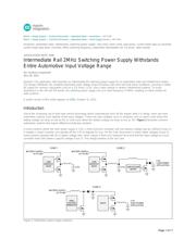
Introduction
Due to the increasing use of start-stop vehicle technology (which automatically turns off the engine while it is idling), more and more
automotive systems must operate at low input voltages. These low input voltages occur in situations such as warm crank (when the
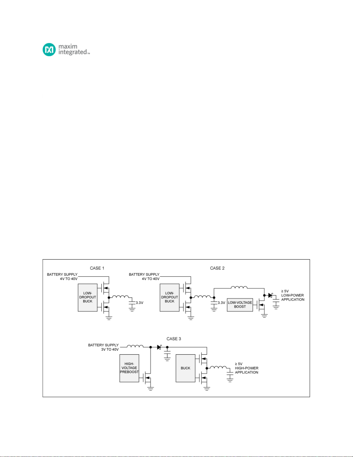
battery voltage can drop as low as 6V) or cold crank (when the battery voltage can drop as low as 3V). Figure 1 illustrates common
automotive systems that require different architecture solutions.
In some systems where the main power supply is 3.3V, a front-end buck converter with low dropout voltage may be sufficient (Case 1).
If needed, a boost converter can operate off the 3.3V to regulate 5V (e.g., for the CAN transceiver) or other higher voltages (Case 2).
Some systems operate with 5V or higher voltage rails, which require a front-end "preboost" to ensure that the input voltage to a buck
converter never falls below a specific voltage (Case 3). This design pertains to the last case.
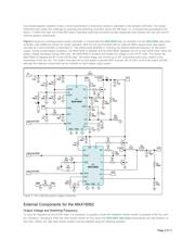
Figure 1. Automotive power-supply solutions.
Page 1 of 11