


herunterladen

Maxim > Design Support > Technical Documents > Application Notes > Amplifier and Comparator Circuits > APP 3668
Maxim > Design Support > Technical Documents > Application Notes > Display Drivers > APP 3668
Maxim > Design Support > Technical Documents > Application Notes > Power-Supply Circuits > APP 3668
Keywords: cree ,nichia,ledtronics,Toyoda,agilent,xlamp,ostar led,high-power led,buck boost led
driver,general lighting led driver,HB LED,HB LED driver,HB LEDs,HB-LED, white led lighting,white leds
,luxeon star,hbled driver,buck led driver,boost led driver,high
APPLICATION NOTE 3668
High-Efficiency Current Drive for High-Brightness
LEDs
Nov 04, 2005
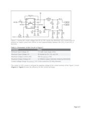
Abstract: This article describes a simple circuit for regulating the current through high-brightness LEDs.
The design includes an off-the-shelf, highly integrated step-down switching regulator (the MAX5035),
which allows accurate control of the LED current. The MAX5035 DC/DC converter operates on a fixed
frequency of 125kHz with wide 7.5V to 76V input-voltage range especially useful for automotive
applications. For brightness control, this converter implements either analog (linear dimming) or low-
frequency duty-cycle modulation (PWM dimming).
Background on High-Brightness LEDs
In recent years, high-brightness (HB) LEDs have gained prominence as the lighting source for a variety
of applications. HB LEDs are rugged and reliable semiconductor devices capable of several tens of
thousands of cycles—up to 100,000 hours of operation. That performance represents an operating life
that is orders of magnitude longer than conventional incandescent and halogen lamps. Thus, HB-LED
applications can be found in automotive lighting, public and commercial signage, and architectural
lighting.
HB LEDs are PN-junction devices especially processed to produce white, red, green, and blue light when
forward biased. (Amber and a few other colors are possible as well.) As PN-junction devices, LEDs
exhibit V-I characteristics similar to those of conventional diodes, but with higher voltage drops across
their junctions. Little current passes through an LED until the forward voltage reaches V
F
, which varies
from 2.5V for red LEDs to about 4.5V for blue LEDs. When V
F
is reached, the current increases very
rapidly (as in conventional diodes). Consequently, the designer must employ current limiting to prevent
possible damage. Current limiting can be implemented with three basic methods, each with advantages
and disadvantages (Table 1).
Table 1. Comparison of Current-Limiting Methods
Current-
Limit
Method
Advantages Disadvantages
Power
Loss in
Series
Device¹
It cannot control current accurately.
Page 1 of 7