
herunterladen
Click here for an overview of the wireless
components used in a typical radio
transceiver.
Maxim > Design Support > Technical Documents > Application Notes > Wireless and RF > APP 4256
Keywords: satellite tv, satellite tuner, tuner, vsat, dvb-s, dss, free-to-air, digital video broadcast,
max2112, max2120, p1db, nf, noise figure, cnr, c/n, gain, dynamic range, max2117, max2119
APPLICATION NOTE 4256
Extended Characterization for the
MAX2112/MAX2120 Satellite Tuners
Jul 03, 2008
Abstract: This application note presents typical measured data for the MAX2112/MAX2120 direct-
conversion satellite tuners. The data illustrate the tradeoffs between RF and baseband gain control.
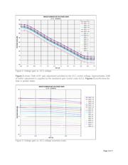
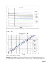
Voltage gain, P
1dB
, noise figure (NF), and carrier-to-noise ratio (CNR) are shown across the RF and
baseband gain-control ranges. Through understanding these tradeoffs, one can optimize an application's
desired dynamic range.
Introduction
This application note provides typical MAX2112/MAX2120
measurement data for voltage gain, P
1dB
, noise figure (NF), and
carrier-to-noise ratio (CNR) across RF and baseband gain-control
ranges. This data is useful for properly distributing the RF and
baseband gain for optimal dynamic range of the satellite receiver
system. To avoid tuner saturation for strong signal reception, a
high P
1dB
is needed. Weak signal reception requires low NF.
Appropriate tradeoffs between these competing requirements result
in the optimal dynamic range.
Operational Overview
The MAX2112/MAX2120 direct-conversion tuner ICs are designed for satellite set-top and VSAT
applications. Each IC is intended for QPSK, Digital Video Broadcast (DVB-S), DSS, and free-to-air
applications.
The MAX2112/MAX2120 directly convert satellite signals from the LNB to baseband using a broadband
I/Q downconverter. Their operating frequency range extends from 925MHz to 2175MHz.
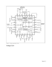
Figure 1 shows a typical operating circuit for the devices. Pin 4 is the RF input. Pins 17 to 20 are the
differential baseband outputs. A RF gain control voltage (GC1) is applied to pin 5; typically, this voltage is
a filtered PWM output from the demodulator IC. In a closed-loop system, the filtered PWM output forces
a constant amplitude signal (typically 1V
P-P
) at the devices' I/Q outputs. The baseband gain is controlled
by a programmable code (GC2). Typically, an optimal value for GC2 is selected and held constant for a
particular receiver system.
Page 1 of 11