
herunterladen
Click here for an overview of the wireless
components used in a typical radio
transceiver.
Maxim > Design Support > Technical Documents > Application Notes > Wireless and RF > APP 3908
Keywords: DAB,T-DMB,DMB,Digital Radio,Digital Media Broadcast,Digital Audio Broadcast,MAX2170
APPLICATION NOTE 3908
MAX2170/MAX2171 DAB/T-DMB Digital Radio Tuner
Sep 22, 2006
Abstract:
This application
note introduces the DAB and T-DMB standards for digital-audio broadcast and cell-phone
TV plus music, respectively. A DAB/T-DMB receiver incorporating the MAX2170/MAX2171 tuner is described.
Introduction
Digital-audio broadcast (DAB) is a European digital-audio broadcast standard
for Europe, Asia, and Canada. DAB is defined for mobile, stationary and
portable receivers. T-DMB (terrestrial digital multimedia broadcast) is a Korean
standard for mobile TV and music. T-DMB uses the DAB standard for RF
requirements. RF broadcast is in the VHF-III band and L-band using coded
orthogonal frequency division multiplexing (COFDM). The MAX2170/MAX2171¹
DAB/T-DMB tuner converts a desired RF broadcast channel to a low-IF
frequency that is supplied to a demodulator.
DAB/T-DMB Receiver Incorporating the MAX2170/MAX2171 Tuner
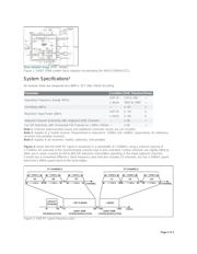
Figure 1 shows a typical DAB/T-DMB receiver block diagram based on the MAX2170/MAX2171 direct-conversion to
low-IF tuner and a demodulator/decoder. The tuner converts the RF input to a 2.048MHz low-IF output. The low-IF
signal enters the demodulator where it is sampled by an ADC, demodulated, and decoded. The output of the
demodulator is a MPEG-2 Transport Stream (TS).
The integrated tuner covers the input frequency ranges of 168MHz to 230MHz and 1452MHz to 1492MHz (VHF-III
and L-band). A single-antenna input is fed into the RF IN connector that supplies both VHF and L-band filter paths.
A VHF tracking filter minimizes the affects of distant blockers. Similarly, the distant blockers are minimized for L-
band by a low-loss, fixed passband, ceramic bandpass filter. An integrated variable passband of the VHF tracking
filter is necessary because of the much wider percent bandwidth required in the VHF band. An RF switch selects
either the VHF or the L-band path and the RF gain is adjusted in the RF VGA. Then the tuner directly converts the
RF signal to baseband and subsequently remodulates it to provide a balanced low-IF output centered at 2.048MHz.
This architecture enables implementation of integrated lowpass filtering at baseband to eliminate the IF SAW filter.
An integrated power detector typically controls the RF VGA, although demodulator control is also possible. Low-IF
VGA control is provided by the demodulator.
The MAX2170/MAX2171 VCO architecture optimizes both close-in and wide-band phase noise for COFDM
applications where sensitivity to both 1kHz phase noise and wide-band phase noise related to strong adjacents can
be a problem. FM reception is also possible using the integrated filter by setting it to cover the 87MHz to 108MHz
frequency range.
The only difference between the MAX2170 and the MAX2171 is the buffered reference oscillator output frequency.
The MAX2170 reference output is the same as the crystal frequency; whereas, the MAX2171 reference output is
one-third of the crystal frequency. These two reference output options allow use with demodulators that accept only
one or the other. The 24.576MHz crystal frequency or a divided version of it is universal for DAB demodulation. A
typical ADC sample clock frequency of 8.192MHz (24.576MHz/3) is a tradeoff between satisfying the Nyquist
criterion with margin and reducing power consumption by selecting a low frequency.
Page 1 of 3