

herunterladen
Maxim > Design Support > Technical Documents > Application Notes > Analog Switches and Multiplexers > APP 4539
Keywords: A/D converters, ADCs, A/D converter calibration, offset flipping, handheld devices
APPLICATION NOTE 4539
Precise Calibration of Dual-Slope ADCs
Jan 13, 2011
Abstract: This circuit calibrates ADCs on-the-fly, using analog switches to configure the setup properly for
obtaining the zero and span output codes.
A similar version of this article appeared in the December 31, 2007 issue of EE Times magazine.
Handheld devices for measuring toxic gas, blood glucose, etc. are increasingly popular, and their low cost has
made them throwaway devices, to be discarded when the battery or the sensor expires. Typical devices
include a lithium (Li) primary cell, a sensor, an A/D converter (ADC), conditioning circuitry, a microcontroller
unit (MCU), and an LCD. To minimize cost, the design often employs simple LED indicators, a low-cost 8-pin
MCU, and a discrete dual-slope ADC. This note explains the use of "offset flipping" for on-the-fly calibration
of the ADC.
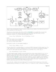
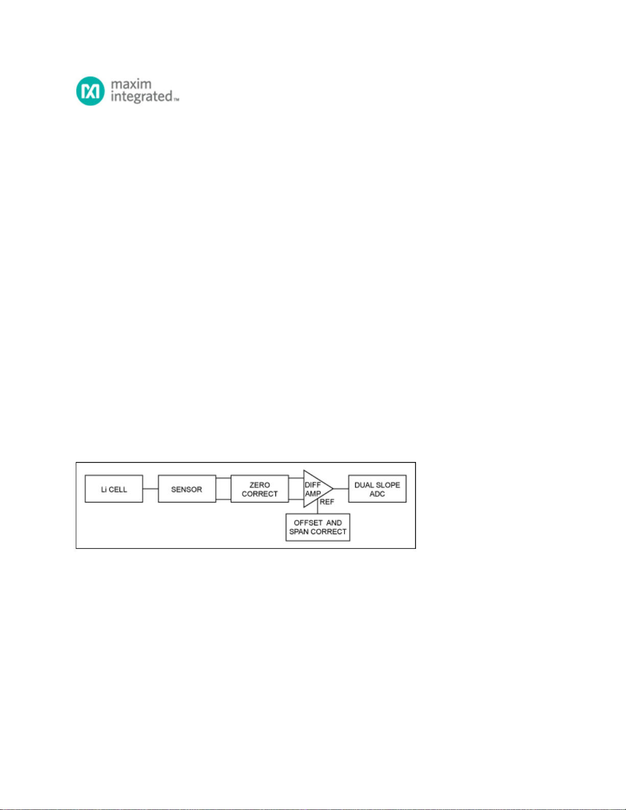
A block diagram of the circuit (Figure 1) includes a single primary Li cell, a millivolt-output bridge sensor, a
differential amplifier, and the dual-slope ADC, plus correction circuitry for offset, zero, and span. Component
values are selected on assumption that the Li-cell voltage ranges from 2.2V to 3.6V. Because that voltage
serves as bias for the bridge and also as reference for the ADC, the ADC input and its full-scale output
(span) move together as the cell voltage changes. This ratiometric configuration minimizes error and
eliminates the need for a precision voltage reference.
Figure 1. Block diagram of the slope-ADC calibration circuit.
The sensor (S1) produces 20mV/V at full scale (Figure 2). For a 3.6V Li cell, therefore, the output is 20mV/V
× 3.6V = 72mV. The dual op amp (U2, MAX4242) draws only 18µA of quiescent current per amplifier. Its
outputs swing rail-to-rail, and operate down to 1.8V. U2A is configured as a standard differential amplifier with
gain of 30. Operating with a 3.6V lithium cell, it achieves a full-scale output of 2.160V. (Note that the resistor
network around a differential amplifier loads the input-signal source (sensor), so the sensor should have a
low output impedance. If not, you should buffer the sensor with an instrumentation amplifier or equivalent.)
Page 1 of 3