
herunterladen

Maxim > Design Support > Technical Documents > Application Notes > Digital Potentiometers > APP 4101
Keywords: Digital, Potentiometer,analog, control, resistor, nonvolatility, wiper, debounce, gain, DAC,
digipot
APPLICATION NOTE 4101
Differentiating Digital Potentiometer Features
Sep 24, 2007
Abstract: Digital potentiometers (digipots) facilitate digital control and adjustment of resistances, voltages,
and currents in analog circuitry for a wide range of applications. This application note presents the basic
functionality of digipots. The article also explains how digipots can be modified and features added to
enhance system performance, simplify designs, and meet the requirements of a specific application.
Introduction
Digital potentiometers, or digipots, facilitate digital control and adjustment of resistances, voltages, and
currents in analog circuitry. Common digipot applications include power-supply calibration, audio volume
control, brightness control, gain adjustment, and control of bias and modulation currents in optical
modules. Beyond basic digipot specifications, there are a number of features that can improve system
performance and simplify designs. Among these features are various types of nonvolatility, zero-crossing
detection, debounced pushbutton interfaces, temperature compensation, and write protection. The
relevance of each of these features varies with the application.
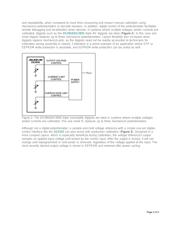
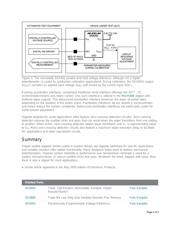
Basic Digipot Design
A true potentiometer is a three-terminal device (see Figure 1a). The low terminal, V
L
, is either internally
connected to device ground or pinned out for design flexibility. This three-terminal digipot configuration is
essentially an adjustable resistive divider with a fixed, end-to-end resistance.
A variable resistor is a two-terminal digipot variant with the wiper and one end of the resistor string
available (see Figure 1b). Adjusting the position of the wiper in a variable-resistor digipot configuration
effectively modifies the end-to-end resistance of the digipot.
Figure 1. (a) A three-terminal digipot configuration is essentially an adjustable resistive divider with a
Page 1 of 5