
herunterladen
Maxim > Design Support > Technical Documents > Application Notes > Circuit Protection > APP 4290
Maxim > Design Support > Technical Documents > Application Notes > Digital Potentiometers > APP 4290
Maxim > Design Support > Technical Documents > Application Notes > General Engineering Topics > APP 4290
Keywords: Initial accuracy, digital pots, potentiometer, end-to-end tolerance, resistance, voltage, dividers,
ratiometric, ratio, steps, LSB, taps, error, temperature, coefficient, series resistor, noise, change,
reference, buffer, amplifier
APPLICATION NOTE 4290
Ratiometric Design Overcomes the 25% Tolerance
of a Digital Potentiometer
By: Bill Laumeister, Strategic Applications Engineer
Sep 23, 2008
Abstract: This application note explains how to eliminate the voltage change when a digital potentiometer
is used as a voltage-divider in series with other resistors.
Introduction
Mechanical and electronic digital potentiometers tend to have loose end-to-end tolerances. Maxim digital
pots typically have a 20% to 30% resistance tolerance. The resistance tolerance can be problematic
when the digital pot is used as a voltage-divider in series with other resistors. That configuration will
result in an unacceptable voltage change over tolerance.
This application note discusses a ratiometric method to convert that resistance tolerance into an
acceptable current change. The proposed design also effectively removes the voltage change. In the
circuit presented here the voltage output depends only on the ratio of the steps of the pot. The
temperature coefficient is better controlled in the design.
Ratiometric Method for the Design
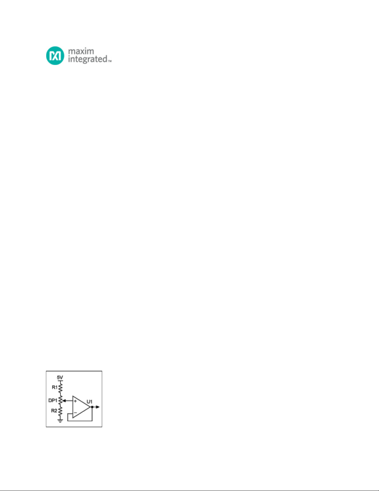
The design challenge is straightforward: a variable voltage between 3V and 4.5V with a tolerance of 3%.
Start with the schematic in Figure 1 and do the math. The digital pot is 50kΩ (25% tolerance); R1 is
16.5K (1%) and R2 is 100K (1%). The 25% tolerance of the pot's end-to-end resistance will dominate in
this design.
Figure 1. Basic schematic.
Page 1 of 3