

herunterladen

Maxim > Design Support > Technical Documents > Application Notes > Amplifier and Comparator Circuits > APP 4479
Maxim > Design Support > Technical Documents > Application Notes > Display Drivers > APP 4479
Maxim > Design Support > Technical Documents > Application Notes > LED Lighting > APP 4479
Keywords: high-brightness LEDs, HBLEDs, forward voltage, differential measurments, LED drivers, comparators
APPLICATION NOTE 4479
Diagnose LEDs by Monitoring the Switch-Mode Duty
Cycle
By: Fons Janssen, Senior Member of the Technical Staff
Jul 30, 2010
Abstract:
A change
in the forward voltage (V
F
) for a string of series-connected, high-brightness LEDs (HB LEDs) can
indicate deterioration or complete failure of one or more of the LEDs. Accordingly, this circuit assesses the LED's
health by monitoring V
F
.
A similar version of this article appeared in the April 4, 2009 issue of EDN magazine.
The forward voltage (V
F
) of high-brightness LEDs (HB LEDs) is often monitored to assess the health of the LED. Big
changes in V
F
can indicate deterioration or even a complete failure of one or more LEDs connected in series.
For several LEDs in series, the sum of their V
F
voltages can go to 40V or more, and if not referenced to ground, that
V
F
sum requires a differential measurement. As a third challenge (in addition to high voltage and differential
measurement), HBLEDs are often dimmed using pulse-width modulation (PWM). If so, you can't measure V
F
during
the low portion of the PWM duty cycle, when the LEDs are not illuminated and V
F
is not present. For a hysteretic buck
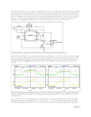
LED driver (MAX16820) driving three LEDs in series (Figure 1), you must measure the anode and cathode voltages of
the string when DIM is high.
Figure 1. Standard driver circuit for HB LEDs.
To avoid the need for a differential high-voltage measurement, you can take the indirect approach of measuring the
duty cycle at the DRV pin. For this particular LED driver, a first-order estimate of forward voltage for the LED string is
V
F
= D × V
IN
, where D represents an internal duty cycle produced in the IC's switchmode section (not to be confused
with the duty cycle at DIM). The DRV signal is referenced to ground and limited to V
CC
(5V). That condition allows the
use of low voltage ADCs or comparators, which in turn can be powered by the LED driver's V
CC
output (10mA
maximum).
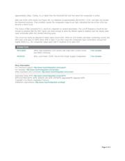
Figure 2 shows how to detect a short-circuited LED with the aid of a comparator (MAX9141). Filter R
1
C
1
converts the
Page 1 of 3