


herunterladen

Maxim > Design Support > Technical Documents > Application Notes > Basestations/Wireless Infrastructure > APP 873
Maxim > Design Support > Technical Documents > Application Notes > High-Speed Interconnect > APP 873
Maxim > Design Support > Technical Documents > Application Notes > Interface Circuits > APP 873
Keywords: LVDS, low voltage, differential signaling signalling, lvds, EIA/TIA-644, high speed, clock
distribution, communications, stubs, EMI, electro-magnetic immunity, fail-safe, noise immunity, low power
APPLICATION NOTE 873
High-Speed Signal Distribution Using Low-Voltage
Differential Signaling (LVDS)
Dec 11, 2001
Abstract: The ANSI EIA/TIA-644 standard for Low Voltage Differential Signaling (LVDS) is well suited for
a variety of applications including clock distribution, point-to-point and point-to-multipoint signal
distribution. This note describes methods for distributing high-speed communications signals to different
destinations using LVDS signaling.
Low-voltage differential signaling (LVDS) is well-suited for a variety of applications, including clock
distribution and point-to-multipoint signal distribution. This note describes methods for distributing high-
speed signals to different destinations.
Clock distribution is of great importance in digital systems where different subsystems are required to
work with the same clock reference. For example, the DSP section of a basestation must, in most cases,
be synchronized to the radio-frequency signal processing section, which is where phase-locked loops
(PLLs) produce the required local oscillator frequencies and where analog-to-digital converters are
locked to the central clock reference. Also, when working with applications that include radio receivers,
the clock (and the signals) must be distributed with the lowest possible emission levels to avoid
interfering with low-level signal paths.
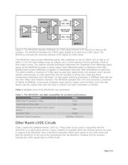
When distributing high-speed signals to different destinations, various strategies can be employed. Two
approaches represent the extremes within which you find the range of strategies: one, driving all
destinations from a single source/driver (called "multi-drop distribution"); two, using a separate driver for
each destination (called "multiple point-to-point distribution"). Figure 1 shows the difference between
these two types of distribution with two typical techniques. In multi-drop distribution, a driver of sufficient
drive capability drives all receivers and the intervening media (cable, connectors(s), backplane). The bus
is usually terminated in its characteristic impedance at the final receiver. Efforts must be made to keep
all "stubs" or branches from the bus as short as possible to avoid possible signal integrity problems. On
the high-density printed circuit boards of today, controlling stub length is not always simple.
Page 1 of 5