
herunterladen

Maxim > Design Support > Technical Documents > Application Notes > Amplifier and Comparator Circuits > APP 3223
Keywords: semiconductor toggle switch, on-off switch, single button, portable equipment, portable
devices, toggle switch, latching function, comparator
APPLICATION NOTE 3223
Semiconductor Toggle Switch
By: Kevin Bilke, Applications Engineer
Jun 23, 2004
Abstract: A low-power circuit formed with resistors, capacitors, a pushbutton switch, and two comparators
serves as a toggle switch that directly drives loads up to 40mA, providing a known state following power
up, battery insertion, or system timeout.
We are all used to single button on-off switches on portable appliances such as mobile (cellular) phones.
The single button has several advantages over a toggling switch that delivers battery power directly to
the electronics:
It takes up less front panel space.
It requires just one low-current, SPST, momentary-contact switch, which is typically more reliable,
less expensive and requires simpler assembly.
Power is delivered by circuitry rather than a pair of contacts that go straight to the battery.
Protection can be provided against contact bounce and power glitches when batteries are inserted
and removed, or when AC supplies are connected and disconnected.
Orderly power-up and power-down sequences can be controlled by a microcontroller or other
circuitry, which is has separate power available.
On products that include a microcontroller or microprocessor, this is normally implemented in a software
routine. In simpler equipment, a latching circuit must be provided. This application note describes such a
circuit.
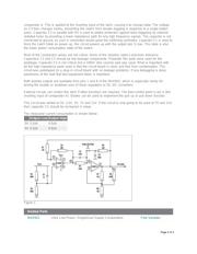
The circuit below is a semiconductor toggle switch. The output state toggles in response to the
pushbutton. It powers-up in a known state. It can directly drive a switched load or the enable or
shutdown pins of a regulator (DC-DC converter or linear regulator).
The circuit is based on a MAX922, a dual comparator in an 8-pin package (DIL or surface-mount). The
MAX922 is ideal for this application. It has a very low current consumption (2.5uA), wide supply range
(2.5 to 11V), low input bias currents (10pA, allowing high impedance passive components) and its
outputs can directly source loads up to 40mA.
The circuit is best explained by first ignoring C1 and C2.
Comparator A forms a latch. Comparator B is used to reinforce the drive to the latch input. This is
weakly driven so it can be shifted by the push button.This drive is important - without it, the input could
just float to a new value or the input would be open to stray signals and noise.
The RC network formed by R6 and C3 is used to store the current value of the latch built around
Page 1 of 3