


herunterladen
Maxim > Design Support > Technical Documents > Application Notes > Automatic Test Equipment (ATE) > APP 5141
Keywords: SPICE, simulation, cable model, skin effect, lumped model, transmission line, dielectric loss
APPLICATION NOTE 5141
An Improved and Simple Cable Simulation Model
By: Bernard Hyland, Senior Member of Technical Staff
Oct 22, 2012
Abstract:
Nonideal cable dispersive
effects can affect system performance. This application note discusses the two
main loss effects related to cables (skin-effect and dielectric losses), and presents a simple method of modeling the
cable for use in standard SPICE simulators.
A similar version of this article appears on EDN, July 30, 2012.
Introduction
Cables are used in many high-frequency board designs and can become a critical element in the signal path. This is
especially true for signals that exceed 500MHz. If not modeled as part of that system, cables can lead to unexpected
system performance degradation and to costly time delays in debugging and corrections. Even with this understood,
cables are notoriously difficult to model correctly. Using a simple transmission line model may not effectively model this
element because it is difficult to model a cable both in the frequency and the time domains.
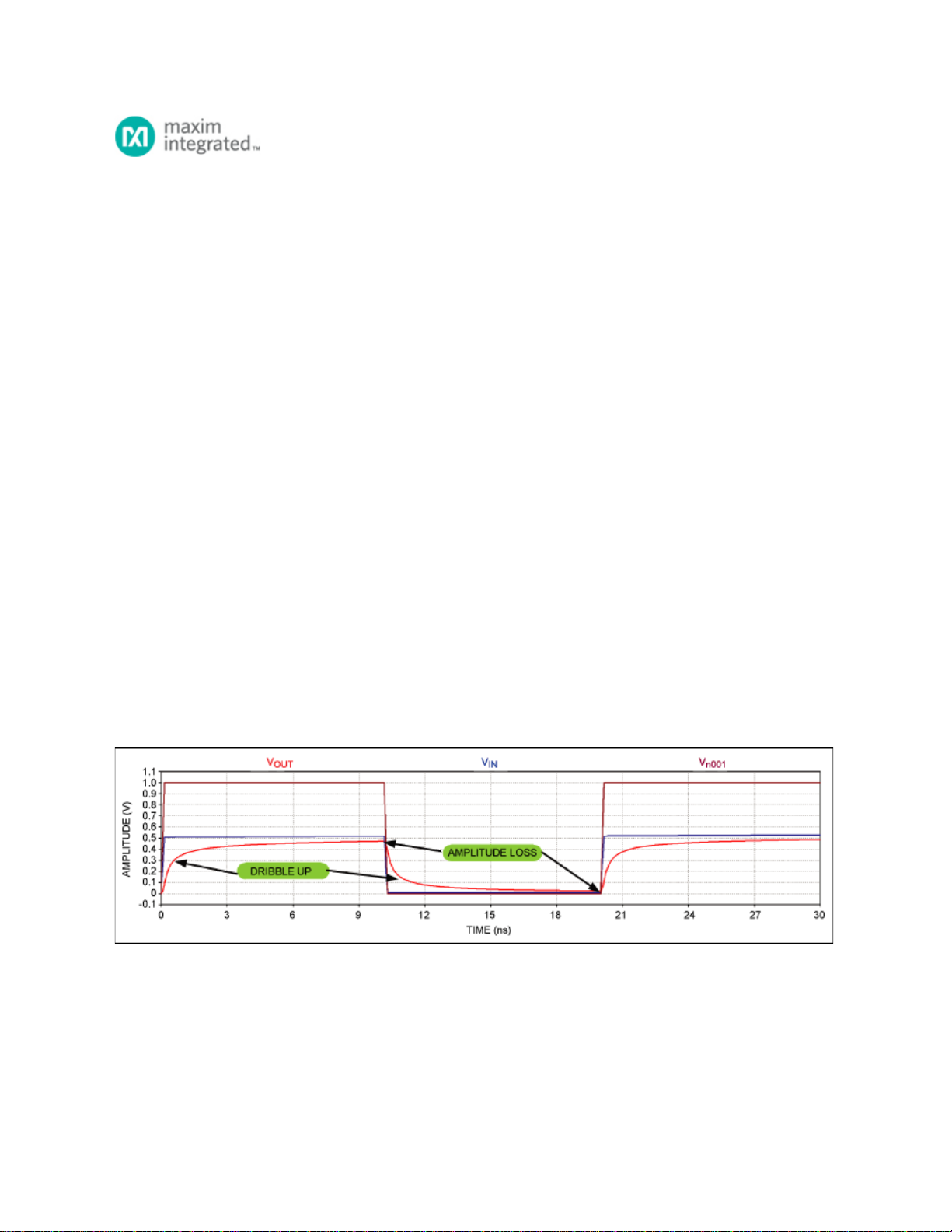
Cable nonideal dispersive effects can affect system performance. These cable effects are seen¹ on drivers, buffers, and
comparators. In the driver or buffer, the low-frequency dribble up (Figure 1) primarily degrades propagation delay
versus pulse-width dispersion; it also degrades minimum pulse time and rise time. In the comparator, the low-
frequency dribble up primarily degrades delay versus pulse width and propagation delay versus overdrive; it also
degrades the minimum pulse width. This application note will discuss the two main loss effects related to cables: the
skin effect and dielectric losses. We will then present a simple method of modeling the cable for use in standard
SPICE simulators.
Figure 1. Example of cable loss effects (simulated results from Figure 3 below).
Why Model a Cable?
As frequencies start to exceed 500MHz, the cable starts to noticeably impact the bandwidth of the signal path and
begins to degrade this path in many ways. To understand the effects of cables at all frequencies, the cable needs to
be modeled. However, based on that model, more intelligent decisions can be made about the type of cable to be
used. Moreover, the parameters of interest that are being degraded in the signal path can then be understood.
Page 1 of 12