

herunterladen
© Semiconductor Components Industries, LLC, 2016
July, 2016 − Rev. 11
1 Publication Order Number:
MC10E116/D
MC10E116, MC100E116
5 V ECL Quint Differential
Line Receiver
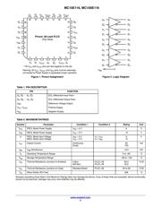
Description
The MC10E/100E116 is a quint differential line receiver with
emitter-follower outputs. For applications which require bandwidths
greater than that of the E116, the E416 device may be of interest.
Active current sources plus a deep collector feature of the MOSAIC
III process provide the receivers with excellent common-mode noise
rejection. Each receiver has a dedicated V
CCO
supply lead, providing
optimum symmetry and stability.
If both inverting and non-inverting inputs are at an equal potential of
> −2.5 V, the receiver does not go to a defined state, but rather
current-shares in normal differential amplifier fashion, producing
output voltage levels midway between HIGH and LOW, or the device
may even oscillate.
The V
BB
pin, an internally generated voltage supply, is available to
this device only. For single-ended input conditions, the unused
differential input is connected to V
BB
as a switching reference voltage.
V
BB
may also rebias AC coupled inputs. When used, decouple V
BB
and V
CC
via a 0.01 mF capacitor and limit current sourcing or sinking
to 0.5 mA. When not used, V
BB
should be left open.
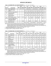
The 100 Series contains temperature compensation.
Features
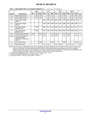
• 500 ps Max. Propagation Delay
• V
BB
Supply Output
• Dedicated V
CCO
Pin for Each Receiver
• PECL Mode Operating Range: V
CC
= 4.2 V to 5.7 V
with V
EE
= 0 V
• NECL Mode Operating Range: V
CC
= 0 V
with V
EE
= −4.2 V to −5.7 V
• Output Qs will default low when inputs are < V
CC
−2.5 V
• Internal Input 50 kW Pulldown Resistors
• Meets or Exceeds JEDEC Spec EIA/JESD78 IC Latchup Test
• ESD Protection:
♦ > 2 kV Human Body Model
♦ > 200 V Machine Model
• Moisture Sensitivity: Level 3 (Pb-Free)
(For Additional Information, see Application Note AND8003/D
)
• Flammability Rating: UL 94 V−0 @ 0.125 in,
Oxygen Index: 28 to 34
• Transistor Count = 98 Devices
• These Devices are Pb-Free, Halogen Free and are RoHS Compliant
MARKING DIAGRAM*
xxx = 10 or 100
A = Assembly Location
WL = Wafer Lot
YY = Year
WW = Work Week
G = Pb-Free Package
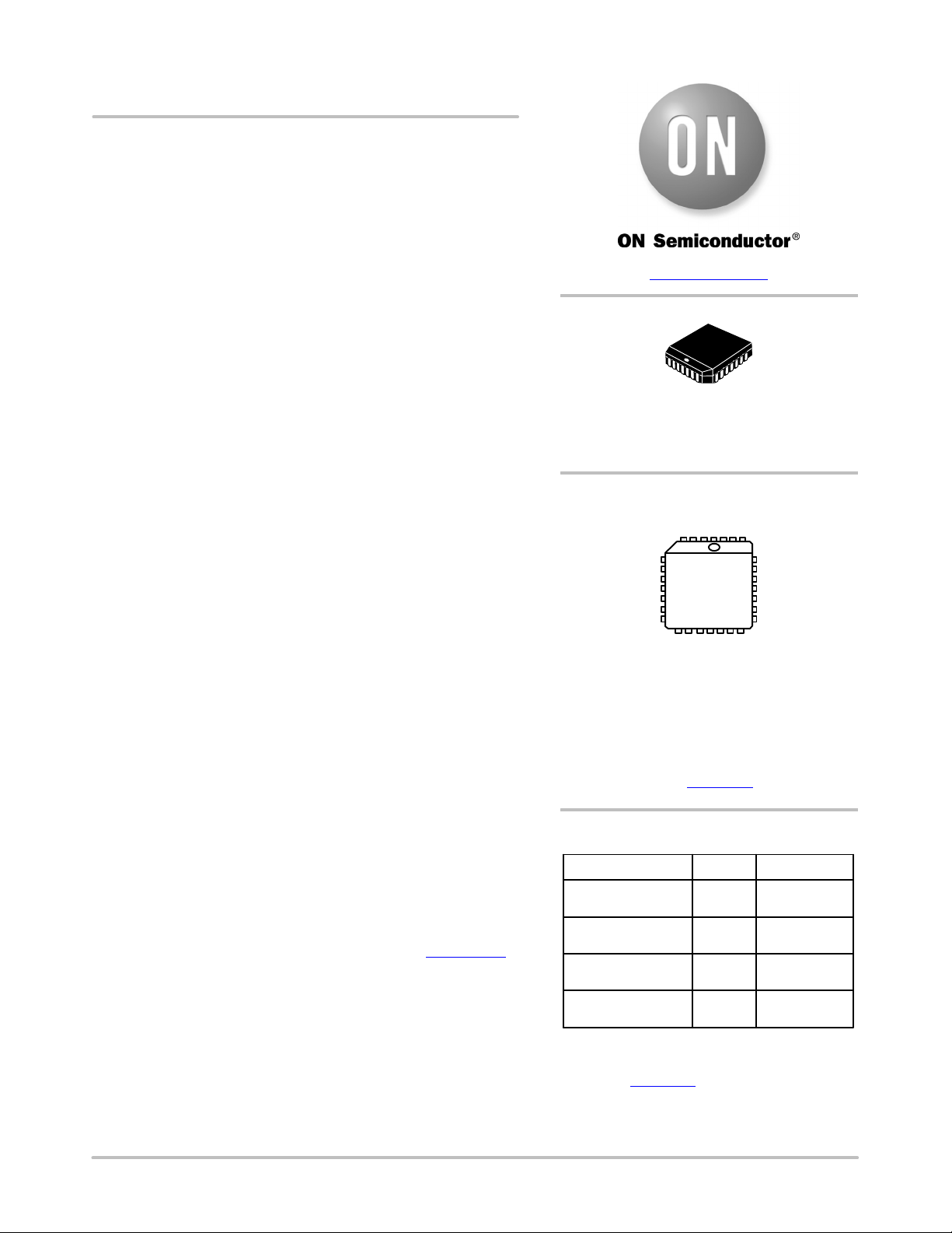
PLCC−28
FN SUFFIX
CASE 776−02
MCxxxE116G
AWLYYWW
1
www.onsemi.com
*For additional marking information, refer to
Application Note AND8002/D
.
ORDERING INFORMATION
Device Package Shipping
MC10E116FNG PLCC−28
(Pb-Free)
37 Units/Tube
MC10E116FNR2G
500 Tape & Reel
MC100E116FNR2G
MC100E116FNG
PLCC−28
(Pb-Free)
PLCC−28
(Pb-Free)
PLCC−28
(Pb-Free)
37 Units/Tube
500 Tape & Reel
†For information on tape and reel specifications, in-
cluding part orientation and tape sizes, please refer
to our Tape and Reel Packaging Specifications
Brochure, BRD8011/D
.
Verzeichnis
- ・ Konfiguration des Pinbelegungsdiagramms on Seite 2
- ・ Abmessungen des Paketumrisses on Seite 7
- ・ Teilenummerierungssystem on Seite 1 Seite 8
- ・ Markierungsinformationen on Seite 1 Seite 6 Seite 8
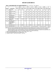
- ・ Typisches Anwendungsschaltbild on Seite 2
- ・ Technische Daten on Seite 1
- ・ Teilenummernliste on Seite 2