

herunterladen

© Semiconductor Components Industries, LLC, 2009
August, 2009 − Rev. 9
1 Publication Order Number:
MC10EL89/D
MC10EL89
5V ECL Coaxial Cable Driver
The MC10EL89 is a differential fanout gate specifically designed to
drive coaxial cables. The device is especially useful in Digital Video
Broadcasting applications; for this application, since the system is
polarity free, each output can be used as an independent driver. The
driver boasts a gain of approximately 40 and produces output swings
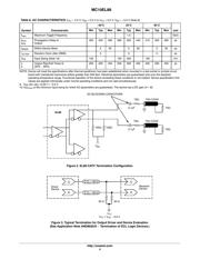
twice as large as a standard ECL output. When driving a coaxial cable,
proper termination is required at both ends of the line to minimize
signal loss. The 1.6 V output swings allow for termination at both ends
of the cable, while maintaining the required 800 mV swing at the
receiving end of the cable. Because of the larger output swings, the
device cannot be terminated into the standard −2.0 V. All of the DC
parameters are tested with a 50 to −3.0 V load. The driver accepts a
standard differential ECL input and can run off of the Digital Video
Broadcast standard −5.0 V supply.
Features
• 375 ps Propagation Delay
• 1.6 V Output Swings
• PECL Mode Operating Range: V
CC
= 4.2 V to 5.7 V with V
EE
= 0 V
• NECL Mode Operating Range: V
CC
= 0 V
with V
EE
= −4.2 V to −5.7 V
• Internal Input Pulldown Resistors
• Pb−Free Packages are Available
Q0
Q0
Q1
Q1 D
D
5
6
7
8
4
3
2
1
V
EE
V
CC
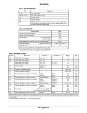
Figure 1. Logic Diagram and Pinout Assignment
*For additional marking information, refer to
Application Note AND8002/D.
MARKING
DIAGRAMS*
A = Assembly Location
L = Wafer Lot
Y = Year
W = Work Week
M
= Date Code
G = Pb−Free Package
HL89
ALYWG
G
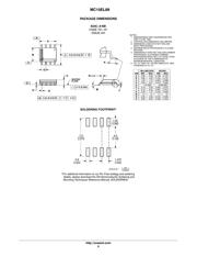
SOIC−8
D SUFFIX
CASE 751
1
8
TSSOP−8
DT SUFFIX
CASE 948R
1
8
1
8
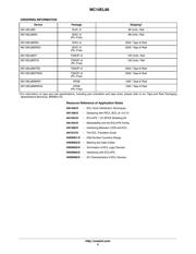
See detailed ordering and shipping information in the package
dimensions section on page 5 of this data sheet.
ORDERING INFORMATION
http://onsemi.com
HEL89
ALYW
G
1
8
DFN8
MN SUFFIX
CASE 506AA
5A M G
G
14
(Note: Microdot may be in either location)
Verzeichnis
- ・ Konfiguration des Pinbelegungsdiagramms on Seite 2
- ・ Abmessungen des Paketumrisses on Seite 6 Seite 7 Seite 8
- ・ Paket-Footprint-Pad-Layout on Seite 6
- ・ Teilenummerierungssystem on Seite 1 Seite 5 Seite 8
- ・ Markierungsinformationen on Seite 1 Seite 5
- ・ Typisches Anwendungsschaltbild on Seite 1
- ・ Technische Daten on Seite 5