
herunterladen

* This document contains certain information on a new product.
Specifications and information herein are subject to change without notice.
Document Number: PF3001
Rev. 2.0, 8/2016
NXP Semiconductors
Data sheet: Advance Information
© 2016 NXP B.V.
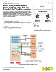
Power management integrated
circuit (PMIC) for i.MX 7 and i.MX 6
SoloLite/SoloX/UltraLite processors
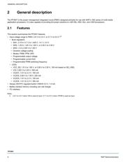
The PF3001 is a SMARTMOS power management integrated circuit (PMIC)
designed specifically for always ON applications with the NXP i.MX 7 and i.MX
6 SoloLite/SoloX/UltraLite application processors. With up to three buck
converters, six linear regulators, RTC supply, and coin-cell charger, the PF3001
can provide power for a complete system, including applications processors,
memory, and system peripherals.
Features:
• Three adjustable high efficiency buck regulators: 2.75 A, 1.5 A, 1.25 A
• Selectable modes: PWM, PFM, APS
• Programmable output voltage, PWM switching frequency, current limit
• Six adjustable general purpose linear regulators
• Input voltage range: 2.8 V to 4.5 V or 3.7 V to 5.5 V
•I
2
C control
• Coin cell charger and always ON RTC supply
• -40 °C to +125 °C Operating Junction Temperature
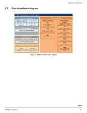
Figure 1. PF3001 simplified application diagram
POWER MANAGEMENT
PF3001
Applications:
•IPTV
• Set top boxes
• POS terminals
• Industrial control
• Medical monitoring
• Home automation/security/energy management
EP SUFFIX
98ASA00719D
48 QFN 7.0 X 7.0
ES SUFFIX
98ASA00933D
48 QFN 7.0 X 7.0
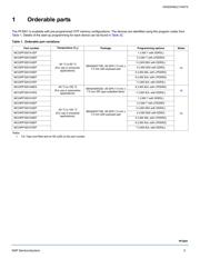
SW3 0.90 – 1.65 V, 1.5A
PF3001
SW1 0.70 – 3.30 V, 2.75A
SW2 1.50 – 1.85 V
or 2.5 -3.3 V, 1.25A
VLDO1 1.8 – 3.3 V, 100mA
VLDO2 0.8 – 1.55 V, 250mA
VCC_SD 1.8 – 1.85 V
or 2.85 – 3.3 V, 100mA
V33 2.85 -3.3 V, 350mA
VLDO3 1.8 – 3.3 V, 100mA
VLDO4 1.8 -3.3 V, 350mA
Switching regulators
Linear regulators
COINCELL
DDR MEMORY
INTERFACE
i.MX
Parallel control /
GPIOs
I
2
C
USB
Ethernet
CAN
DDR MEMORY
I
2
C
RESETBMCU
PWRON
STANDBY
SD_VSEL
INTB
WAM
GPS/MIPI
LVDS
Display
Cluster/
HUD
Front USB
POD
Rear Seat
Infotainment
Rear USB
POD
Li CELL
Charger
Camera
Sensors
Audio
Codec
Processor
ARM Core
Processor SOC
Camera
GPS
MIPI
Micro PCIe
HDMI
Main Supply
2.8 - 5.5 V
SATA - FLASH
NAND - NOR
Interfaces
SATA
HDD
SD-MMC/
NAND Mem.
External AMP
Microphones
Speakers
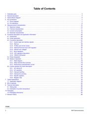
Verzeichnis
- ・ Konfiguration des Pinbelegungsdiagramms on Seite 7 Seite 8 Seite 9
- ・ Abmessungen des Paketumrisses on Seite 83
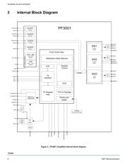
- ・ Blockdiagramm on Seite 5 Seite 6
- ・ Typisches Anwendungsschaltbild on Seite 79
- ・ Beschreibung der Funktionen on Seite 4 Seite 5 Seite 25 Seite 26 Seite 27
- ・ Technische Daten on Seite 1
- ・ Anwendungsbereich on Seite 1 Seite 25 Seite 40 Seite 79
- ・ Elektrische Spezifikation on Seite 13 Seite 16 Seite 43