


herunterladen

Application Report
SLVA546 – January 2013
1
D-CAP2
TM
Frequency Response Model
based on frequency domain analysis of Fixed On-Time with
Bottom Detection having Ripple Injection
Author: Toshiyuki (Rick) Zaitsu, Sales and Marketing, Power Technologist, TI-Japan
Co-Author: Katsuya Goto, Takahiro Miyazaki, Digital Consumer Products, Junichi Yamamoto, Sales and
Marketing, TI-Japan
ABSTRACT
Hysteretic control [2], which is basically non-linear control, has become an important
control method due to its fast transient response. Normal hysteretic control requires a
relatively high-ESR output capacitor. Adding ripple injection to hysteretic control allows
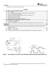
the use of low-ESR ceramic output capacitors [3]-[6]. A “Fixed on-time with bottom
detection having a ripple injection” control topology is shown in Figure 1. This topology,
which is a type of hysteretic control, became popular due to pseudo fixed PWM frequency
operation along with compatibility with low-ESR ceramic output capacitors. It is interesting
that this control method behaves like linear control, showing similarity to a frequency
response (bode-plot) of voltage mode control while keeping wide loop bandwidth, f
bw
.
The frequency domain analysis of the “fixed on-time with bottom detection having ripple
injection” is carried out [1] for the optimal DC-DC converter design based on the
assumption of (a) Averaged model is applicable to a “small-signal analysis” for
frequencies less than the switching frequency and, (b) injected ripple voltage is small
compared to reference voltage. As a result, the comparator with ripple injection shows
single zero (1
st
order lead system) characteristics. The open loop transfer function of the
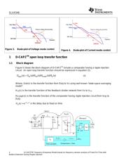
converter is expressed as equation (1). Figure 2 shows the approximated curve of the
frequency response (bode-plot) based on equation (1). The phase increases up toward
+90 degrees due to the single zero, and is a major contributor for the system stability with
wide loop bandwidth. This has advantages compared with conventional linear control
such as voltage mode control (Figure 3) or a current mode control (Figure 4). For these
linear control types, the phase curve is rolling off below 0 degrees in the high frequency
range due to the delay of
sT
e
−
of the PWM and error amplifier compensation circuit.
The operation of D-CAP2
TM
control is similar in concept with this “Fixed On-Time with
Bottom Detection having Ripple Injection”. The difference is that the ripple injection circuit
is integrated on silicon. Therefore, it is stable.