

herunterladen
© Semiconductor Components Industries, LLC, 2014
November, 2014 − Rev. 2
1 Publication Order Number:
AND8123/D
AND8123/D
Power Factor Correction
Stages Operating in Critical
Conduction Mode
This paper proposes a detailed and mathematical analysis
of the operation of a critical conduction mode Power factor
Corrector (PFC), with the goal of easing the PFC stage
dimensioning. After some words on the PFC specification
and a brief presentation of the main critical conduction
schemes, this application note gives the equations necessary
for computing the magnitude of the currents and voltages
that are critical in the choice of the power components.
Introduction
The IEC1000−3−2 specification, usually named Power
Factor Correction (PFC) standard, has been issued with the
goal of minimizing the Total Harmonic Distortion (THD) of
the current that is drawn from the mains. In practice, the
legislation requests the current to be nearly sinusoidal and in
phase with the AC line voltage.
Active solutions are the most effective means to meet the
legislation. A PFC pre-regulator is inserted between the
input bridge and the bulk capacitor. This intermediate stage
is designed to output a constant voltage while drawing
a sinusoidal current from the line. In practice, the step-up (or
boost) configuration is adopted, as this type of converter is
easy to implement. One can just notice that this topology
requires the output to be higher than the input voltage. That
is why the output regulation level is generally set to around
400 V in universal mains conditions.
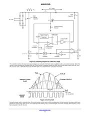
BASICS OF THE CRITICAL CONDUCTION MODE
Critical conduction mode (or border line conduction
mode) operation is the most popular solution for low power
applications. Characterized by a variable frequency control
scheme in which the inductor current ramps to twice the
desired average value, ramps down to zero, then
immediately ramps positive again (refer to Figures 2 and 4),
this control method has the following advantages:
• Simple Control Scheme: The Application Requires Few
External Components
• Ease of Stabilization: The Boost Keeps the First Order
Converter and There is No Need for Ramp
Compensation
• Zero Current Turn On: One Major Benefit of Critical
Conduction Mode is the MOSFET Turn On when the
Diode Current Reaches Zero. Therefore the MOSFET
Switch On is Lossless and Soft and there is No Need
for a Low trr Diode
On the other hand, the critical conduction mode has some
disadvantages:
• Large Peak Currents that Result in High dl/dt and rms
Currents Conducted throughout the PFC Stage
• Large Switching Frequency Variations as Detailed in
the Paper
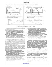
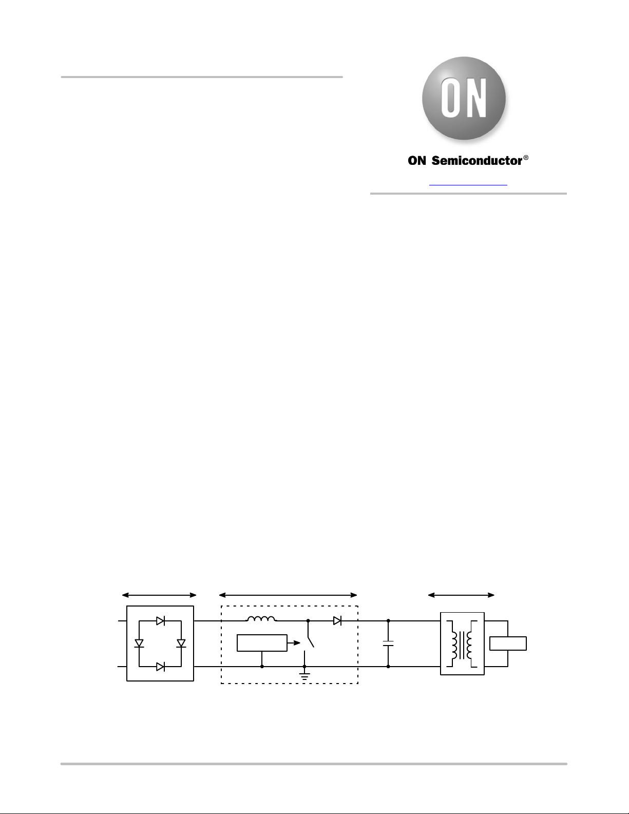
Diode Bridge
IN
+
−
AC
Line
Controller
+
Bulk
Capacitor
LOAD
PFC Stage Power Supply
Figure 1. Power Factor Corrected Power Converter
PFC boost pre-converters typically require a coil, a diode and a Power Switch. This stage also needs a Power Factor Correction controller
that is a circuit specially designed to drive PFC pre-regulators. ON Semiconductor has developed three controllers (MC33262, MC33368 and
MC33260) that operate in critical mode and the NCP1650 for continuous mode applications.
APPLICATION NOTE
www.onsemi.com
Verzeichnis