

herunterladen
© Semiconductor Components Industries, LLC, 2014
September, 2014 − Rev. 15
1 Publication Order Number:
MC74HC4851A/D
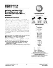
MC74HC4851A,
MC74HC4852A
Analog Multiplexers/
Demultiplexers with
Injection Current Effect
Control
Automotive Customized
These devices are pin compatible to standard HC405x and
MC1405xB analog mux/demux devices, but feature injection current
effect control. This makes them especially suited for usage in
automotive applications where voltages in excess of normal logic
voltage are common.
The injection current effect control allows signals at disabled analog
input channels to exceed the supply voltage range without affecting
the signal of the enabled analog channel. This eliminates the need for
external diode/resistor networks typically used to keep the analog
channel signals within the supply voltage range.
The devices utilize low power silicon gate CMOS technology.
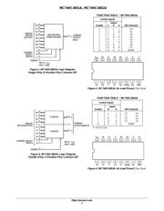
The Channel Select and Enable inputs are compatible with standard
CMOS outputs.
Features
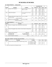
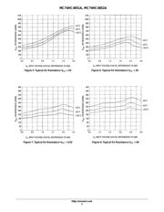
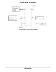
• Injection Current Cross−Coupling Less than 1 mV/mA (See Figure 9)
• Pin Compatible to HC405X and MC1405XB Devices
• Power Supply Range (V
CC
− GND) = 2.0 to 6.0 V
• In Compliance With the Requirements of JEDEC Standard No. 7 A
• Chip Complexity: 154 FETs or 36 Equivalent Gates
• NLV Prefix for Automotive and Other Applications Requiring
Unique Site and Control Change Requirements; AEC−Q100
Qualified and PPAP Capable
• These Devices are Pb−Free, Halogen Free and are RoHS Compliant
http://onsemi.com
MARKING DIAGRAMS
SOIC−16
TSSOP−16
1
16
HC485xAG
AWLYWW
HC48
5xA
ALYWG
G
1
16
x = 1 or 2
A = Assembly Location
WL, L = Wafer Lot
YY, Y = Year
WW, W = Work Week
G or G = Pb−Free Package
SOIC−16 WIDE
1
16
HC4851A
AWLYWWG
See detailed ordering and shipping information in the package
dimensions section on page 11 of this data sheet.
ORDERING INFORMATION
SOIC−16
D SUFFIX
CASE 751B
TSSOP−16
DT SUFFIX
CASE 948F
SOIC−16 WIDE
DW SUFFIX
CASE 751G
(Note: Microdot may be in either location)
Verzeichnis
- ・ Abmessungen des Paketumrisses on Seite 12 Seite 13 Seite 14
- ・ Paket-Footprint-Pad-Layout on Seite 12 Seite 13 Seite 14
- ・ Teilenummerierungssystem on Seite 1 Seite 11 Seite 14
- ・ Markierungsinformationen on Seite 1 Seite 14
- ・ Typisches Anwendungsschaltbild on Seite 2
- ・ Technische Daten on Seite 4 Seite 11
- ・ Anwendungsbereich on Seite 1 Seite 11
- ・ Teilenummernliste on Seite 3