
herunterladen

Freescale Semiconductor Inc.
Data Sheet: Technical Data
Document Number: IMX6DQPAEC
Rev. 1, 03/2016
Package Information
Case FCPBGA 21 x 21 mm, 0.8 mm pitch
Ordering Information
See Table 1
Freescale reserves the right to change the detail specifications as may be required to permit improvements in the
design of its products.
© 2014-2016 Freescale Semiconductor, Inc. All rights reserved.
MCIMX6DPxAxxxxA
MCIMX6QPxAxxxxA
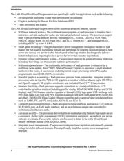
1 Introduction
The i.MX 6DualPlus/6QuadPlus automotive and
infotainment processors represent Freescale
Semiconductor’s latest achievement in integrated
multimedia applications processors.These processors
offer the highest levels of graphics processing
performance in the i.MX 6 series family and are ideally
suited for graphics intensive applications such as
reconfigurable instrument clusters and high performance
infotainment systems.
The i.MX 6DualPlus/6QuadPlus processors feature the
Freescale advanced implementation of the quad
ARM
®
Cortex
®
-A9 core, which operates at speeds up to
1 GHz. They include updated versions of the 2D and 3D
graphics processors, 1080p video processing, and
integrated power management. Each processor provides
a 64-bit DDR3/DDR3L/LPDDR2 memory interface and
a number of other interfaces for connecting peripherals,
such as WLAN, Bluetooth
®
, GPS, hard drive, displays,
and camera sensors.
i.MX 6DualPlus/6QuadPlus
A
utomotive
Applications
Processors
1 Introduction . . . . . . . . . . . . . . . . . . . . . . . . . . . . . . . . . . . . 1
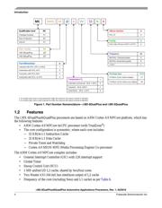
1.1 Ordering Information . . . . . . . . . . . . . . . . . . . . . . . . 3
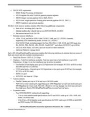
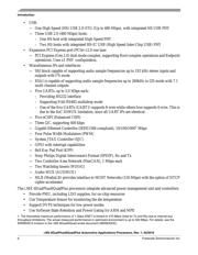
1.2 Features . . . . . . . . . . . . . . . . . . . . . . . . . . . . . . . . . 4
1.3 Signal Naming Convention . . . . . . . . . . . . . . . . . . . 7
2 Architectural Overview . . . . . . . . . . . . . . . . . . . . . . . . . . . 9
2.1 Block Diagram . . . . . . . . . . . . . . . . . . . . . . . . . . . . . 9
3 Modules List . . . . . . . . . . . . . . . . . . . . . . . . . . . . . . . . . . 10
3.1 Special Signal Considerations. . . . . . . . . . . . . . . . 19
3.2 Recommended Connections for Unused Analog
Interfaces. . . . . . . . . . . . . . . . . . . . . . . . . . . . . . . . 19
4 Electrical Characteristics. . . . . . . . . . . . . . . . . . . . . . . . . 20
4.1 Chip-Level Conditions . . . . . . . . . . . . . . . . . . . . . . 20
4.2 Power Supplies Requirements and Restrictions . . 32
4.3 Integrated LDO Voltage Regulator Parameters. . . 33
4.4 PLL Electrical Characteristics . . . . . . . . . . . . . . . . 35
4.5 On-Chip Oscillators . . . . . . . . . . . . . . . . . . . . . . . . 37
4.6 I/O DC Parameters . . . . . . . . . . . . . . . . . . . . . . . . 38
4.7 I/O AC Parameters . . . . . . . . . . . . . . . . . . . . . . . . 42
4.8 Output Buffer Impedance Parameters. . . . . . . . . . 48
4.9 System Modules Timing . . . . . . . . . . . . . . . . . . . . 52
4.10 General-Purpose Media Interface (GPMI) Timing. 67
4.11 External Peripheral Interface Parameters . . . . . . . 76
5 Boot Mode Configuration . . . . . . . . . . . . . . . . . . . . . . . 141
5.1 Boot Mode Configuration Pins. . . . . . . . . . . . . . . 141
5.2 Boot Devices Interfaces Allocation . . . . . . . . . . . 142
6 Package Information and Contact Assignments . . . . . . 144
6.1 Signal Naming Convention . . . . . . . . . . . . . . . . . 144
6.2 21 x 21 mm Package Information . . . . . . . . . . . . 144
7 Revision History . . . . . . . . . . . . . . . . . . . . . . . . . . . . . . 167
Verzeichnis
- ・ Abmessungen des Paketumrisses on Seite 19 Seite 144 Seite 145 Seite 146 Seite 147
- ・ Teilenummerierungssystem on Seite 3 Seite 4
- ・ Blockdiagramm on Seite 9
- ・ Beschreibung der Funktionen on Seite 105
- ・ Technische Daten on Seite 18 Seite 20 Seite 21 Seite 86 Seite 90
- ・ Anwendungsbereich on Seite 2 Seite 3 Seite 4 Seite 5 Seite 6
- ・ Elektrische Spezifikation on Seite 20 Seite 21 Seite 22 Seite 23 Seite 24
- ・ Teilenummernliste on Seite 3