
herunterladen
AN786
DS00786A-page 1
© 2002 Microchip Technology, Inc.
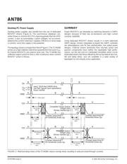
Driving Power MOSFETs in High-Current, Switch Mode Regulators
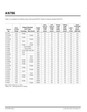
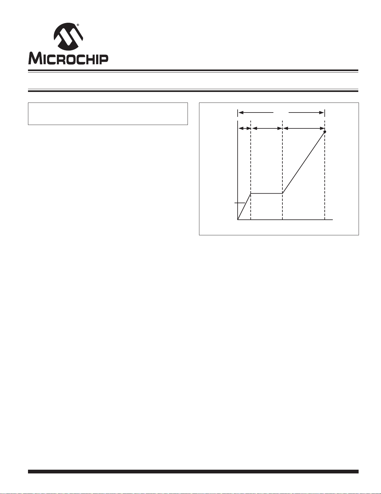
FIGURE 1: Gate charge characteristics.
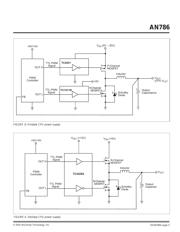
DRIVING THE MOSFET
The low on-resistance and high current carrying capability of power
MOSFETs make them preferred switching devices in SMPS power
supply design. However, designing with these devices is not as
straightforward as with their bipolar counterparts.
Unlike bipolar transistors, power MOSFETs have a considerable
gate capacitance that must be charged beyond the threshold
voltage, V
GS(TH)
, to achieve turn-on. The gate driver must provide
a high enough output current to charge the equivalent gate capaci-
tance, C
EI
, within the time required by the system design.
HOW MUCH GATE CURRENT?
The most common error in calculating gate current is confusing the
MOSFET input capacitance, C
ISS
, for C
EI
and applying the
equation....
I = C(dv/dt)
to calculate the required peak gate current. C
EI
is actually much
higher, and must be derived from the MOSFET manufacturer’s
total gate charge, Q
G
, specifications.
The total gate charge, Q
G
, that must be dispensed into the
equivalent gate capacitance of the MOSFET to achieve turn-on is
given as:
Q
G
= Q
GS
+ Q
GD
+ Q
OD
where:
Q
G
is the total gate charge
Q
GS
is the gate-to-source charge
Q
GD
is the gate-to-drain Miller charge
Q
OD
is the “overdrive charge” after charging
the Miller capacitance.
The curve of Figure 1 is typical of those supplied by MOSFET
manufacturers. Notice that in order to achieve strong turn-on, a V
GS
well above that required to charge C
EI
(and well above V
GS(TH)
) is
required. The equivalent gate capacitance is determined by divid-
ing a given V
GS
into the corresponding total gate charge. The
required gate drive current (for a transition within a specified time)
is determined by dividing the total gate charge by the desired
transition time.
Author: Abid Hussain,
Microchip Technology, Inc.
In equation form:
Q
G
= (C
EI
)(V
GS
)
and
I
G
= Q
G
/t
(transition)
where:
Q
G
is the total gate charge, as defined above
C
EI
is the equivalent gate capacitance
V
GS
is the gate-to-source voltage
I
G
is the gate current required to turn the
MOSFET on in time period t
(transition)
t
(transition)
is the desired transition time
For example:
Given: N-Channel MOSFET
V
GS
= 10V
t (transistion) = 25nsec
Find: Gate drive current, I
G
.
From the MOSFET manufacturer’s specifications, Q
G
= 50nC at
V
GS
= 10V. Using I
G
= Q
G
/t
(transition)
:
I
G
= Q
G
/t
(transition)
= 50 x 10
-9
/25 x 10
-9
= 2.0A
Q
G
, Total Gate Charge (nC)
Q
GS
V
GS
, Gate-to-Source
Voltage (V)
V
GS(TH)
Q
GD
Q
G
Q
OD
Verzeichnis