
herunterladen

2004 Microchip Technology Inc. DS00960A-page 1
AN960
INTRODUCTION
New design methods and components bring high
intelligence to battery charger and power-management
applications. When developing intelligent power
management systems, very complex and cumbersome
analog-only solutions are now old school. When com-
bining low-cost microcontroller’s with analog-attach,
high-speed Pulse Width Modulators (PWMs), the ben-
efits of a mixed signal design can be realized. In the
past, a complex power-management system was
developed using a high-speed analog PWM combined
with logic and specialty analog-only circuits. In some
cases, non-flexible, off-the-shelf solutions are available
for a price. For most applications, they have neither the
features, nor the capability, to meet any special
requirements. With the addition of a microcontroller, the
new design method can adapt to almost any system
command, environmental conditions or system-level
fault.
With the combination of a microcontroller and a high-
speed analog PWM, the designer can enjoy the bene-
fits of programmability with the peace of mind that the
power train is being controlled and protected by a
reliable high-speed analog loop. When external condi-
tions warrant a change in output, the digital microcon-
troller can adjust the output of the supply, the switching
frequency of the supply, the minimum off time of the
power train switch, power-up soft start, take action in
the event of a system-level fault, etc. With the broad
range of Microchip’s PICmicro
®
microcontroller product
line, the microcontroller can be sized for the job. In
many applications, a microcontroller is already
resident. By adding the MCP1630 analog, high-speed
PWM, a power train can be easily added to the design.
This application note will describe a typical intelligent
battery charger power system application. As with most
real life applications, there are many demands made
on the power system designer to protect the system in
the case of battery removal, plugging the battery in
backwards, reverse polarity at the input, a battery
shorting and even more unimaginable situations. A
complete battery charger, fuel gauge system design
will be presented as an example of the mixed signal
design method. Battery reference material and basic
switchmode power supply converter trade-offs are
covered in the beginning of this application note.
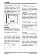
BATTERY BACKGROUND
Definitions:
The anode of a cell during discharge is the negative
electrode. During charge, the anode is the positive
electrode. The anode supplies electrons to the load.
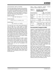
The C rate is the battery’s charge or discharge current
expressed as a multiple of the capacity. For example, if
a battery has a capacity of 500 mAhr, a charge rate (or
“C” rate) of 2C would imply a charge current of 1A.
Capacity is measured in units of Amp-hours and can
be described as the discharge current necessary to
reach the end voltage after one hour.
The cathode of a cell during discharge is the positive
electrode. During charge, the cathode is the negative
electrode. The cathode accepts electrons from the
load.
Charge acceptance is the ability of a battery to accept
charge by converting provided electrical energy into
stored chemical energy.
The electrolyte conducts ions inside the cell between
the anode and the cathode. The electrolyte must be a
good ionic conductor but not be electrically conductive,
since this would cause short-circuiting. Most
electrolytes are liquids, although some are solids.
Memory effect is a temporary failure of a battery due
to repeated incomplete discharge. This causes the
battery to lose capacity. Capacity can be restored by a
few repeated cycles of full discharge and charge.
Self-discharge is the loss of charge of an unloaded
cell due to internal chemical reactions.
The service life of a secondary battery is defined as
the length of useful performance in years, called float
life, or the number of times it can be usefully charged
and discharged, called cycle life.
Trickle charge is a low charge rate used to maintain a
battery in a fully charged condition.
Author: Terry Cleveland and
Catherine Vannicola,
Microchip Technology Inc.
New Components and Design Methods Bring Intelligence to
Battery Charger Applications
Verzeichnis
- ・ Technische Daten on Seite 8
- ・ Anwendungsbereich on Seite 1