

herunterladen
© 2009 Microchip Technology Inc. DS00994B-page 1
AN994
OVERVIEW
The MCP3905A/06A energy-metering Integrate
Circuits (ICs) supply active real power measurements
for single-phase residential meter designs. These
devices include features specific for the International
Electrotechnical Commission (IEC) requirements, such
as no-load threshold and start-up current. In addition,
the MCP3905A/06A Energy Meter Reference Design
demonstrates a system-level design that passes EMC
immunity requirements per the IEC standard.
EMC testing for IEC compliance was performed on the
Energy Meter Reference Design Demonstration Board
used in this application note. These tests were
performed by a third party, the results of which are
included at the end of this application note.
Accuracy tests were also performed by a third party
using the MCP3905A device across current ranges,
power factors, V
DD
and line frequency conditions
outlined in the IEC standard. The results of these tests
are also included in the "Summary".
This application note can be used for both
MCP3905A/06A stand-alone meters and PICmicro
®
microcontroller-based meters using the
MCP3905A/06A devices as the Analog Front-End
(AFE). In both meter designs, the system accuracy and
EMC immunity rely on the AFE design. Examples of
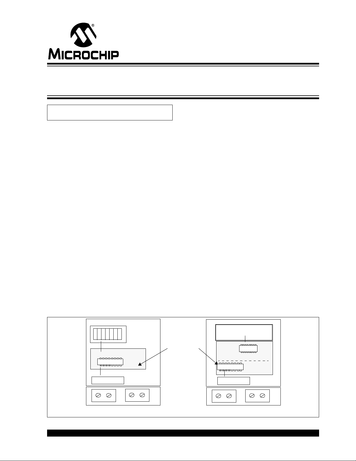
both meter types are shown in Figure 1.
GOALS
The goal of this application note is to discuss design
decisions relating to meter design when using the
MCP3905A or MCP3906A device that will lead to IEC
compliance.
Meter ratings and current sensor choices are
discussed first. The trade-off between shunts and
Current Transformers (CTs) is described, as well as
how the more accurate MCP3906A can be used as an
advantage in meter design. This application note will
focus on the shunt as a current-sensing choice and
contains sections for compensation relating to the
shunt only.
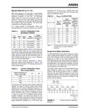
Proper selection of the PGA gain is covered, describing
how shunt sizes, power consumption goals and signals
with high crest factors guide this decision. Directions
follow that describes how to select the proper output
frequency and calibrate the meter using single-point
calibration to a typical meter constant of 100 imp/kWh
(impulses/kilowatt hour).
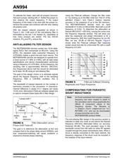
System-level design decisions follow, including EMC
compliance and LRC filter design. Microchip’s free
FilterLab
®
design tool is used to show anti-aliasing filter
design and phase-shift trade-offs. A spreadsheet with
complex frequency analysis is included to assist in the
compensation calculations, best showing graphically the
effects of component values in the frequency domain.
Power supply design is also discussed, including how
to choose capacitor values based on meter-specific
current requirements.
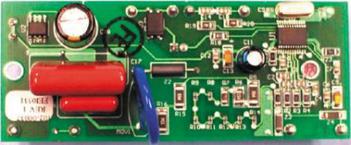
FIGURE 1: MCP3905A/06A Stand-Alone Energy Meter and Microcontroller-Based Energy Meter.
Author: Craig L. King
Microchip Technology Inc.
MCP3905A/06A
8
9
0
1
8
9
0
1
8
9
0
1
4
5
6
7
8
9
0
1
2
3
4
5
2
3
4
5
MCP3905A/06A
current-sensing
element
current-sensing
element
CLASS 1 METER 5(40)a
POWER = 1432 KW
ENERGY = 43213 kWh
28/03/2004
15:23:23
Analog
Digital
MICRO
Reference Design
MCP3905A Stand-Alone Mechanical Counter
Energy Meter
Microcontroller with LCD Energy Meter
1000 imp/kWh
CLASS 1 METER
5(40)a
MCP3905A/06A
IEC Compliant Active-Energy Meter Design
Using The MCP3905A/06A