
herunterladen
HCMOS Crystal Oscillators
With the advent of high speed HCMOS circuits, it is possible
to build systems with clockratesof greater than 30 MHz.The
familiar gate oscillator circuits used at low frequencies work
well at higher frequencies and either L–C or crystal resona-
tors maybe used depending on the stability required. Above
20 MHz, it becomes expensive to fabricate fundamental
mode crystals, so overtone modes are used.
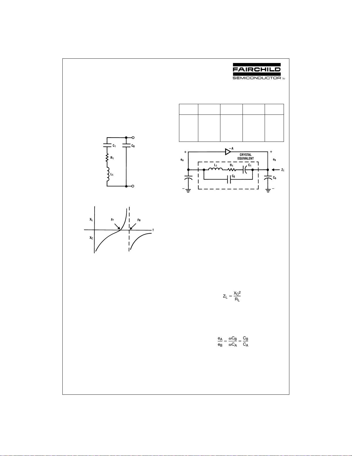
Basic Oscillator Theory
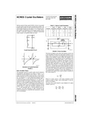
The equivalent circuit of a quartz crystal, and its reactance
characteristics with frequency are shown in
Figure 1
.F
R
is
called the resonant frequency and is where L
1
and C
1
are in
series resonance and the crystal looks like a small resistor
R1. The frequency F
A
is the antiresonant frequency and is
the point where L
1
–C
1
look inductive and resonate with C
O
to form the parallel resonant frequency F
A
,F
R
and F
A
are
usually less than 0.1
%
apart. In specifying crystals, the fre-
quency F
R
is the oscillation frequency to the crystal in a se-
ries mode circuit, and F
R
is the parallel resonant frequency.
In a parallel mode circuit, the oscillation frequency will be
slightly below F
A
where the inductive component of the
L
1
–C
1
arm resonates with C
O
and the external circuit ca-
pacitance. The exact frequency is often corrected by the
crystal manufacture to a specified load capacitance, usually
20 or 32 picofarads.
TABLE 1. Typical Crystal Parameters
32 kHz 200 kHz 2 MHz 30 MHz
Parameter fundamental fundamental fundamental overtone
R
1
200 kΩ 2kΩ 100 Ω 20 Ω
L
1
7000H 27H 529 mH 11 mH
C
1
0.003 pF 0.024 pF 0.012 pF 0.0026 pF
C
0
1.7 pF 9 pF 4 pF 6 pF
Q 100k 18k 54k 100k
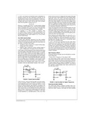
The Pierce oscillator is one of the more popular circuits, and
is the foundation for almost all single gate oscillators in use
today. In this circuit,
Figure 2
, the signal from the input to the
output of the amplifier is phase shifted 180 degrees. The
crystal appears as a large inductor since it is operating in the
parallel mode, and in conjunction with C
A
and C
B
, forms a pi
network that provides an additional 180 degrees of phase
shift from output to the input. C
A
in series with C
B
plus any
additional stray capacitance form the load capacitance for
the crystal. In this circuit, C
A
is usually made about the same
value as C
B
, and the total value of both capacitors in series
is the load capacitance of the crystal which is generally cho-
sen to be 32 pF, making the value of each capacitor 64 pF.
The approximation equations of the load impedance, Z
1
,
presented to the output of the crystal oscillator’s amplifier by
the crystal network is:
Where X
C
=
−j/ωC
B
and R
L
is the series resistance of the
crystal as shown in Table I. Also ω
=
2πf where f is the fre-
quency of oscillation.
The ratio of the crystal network’s input voltage to it’s output
voltage is given by:
AN005347-1
Crystal Equivalent Circuit
AN005347-2
Reactance of Crystal Resonator
FIGURE 1.
AN005347-3
FIGURE 2. Pierce Oscillator
Fairchild Semiconductor
Application Note 340
May 1983
HCMOS Crystal Oscillators AN-340
© 1998 Fairchild Semiconductor Corporation AN005347 www.fairchildsemi.com