


herunterladen

© Semiconductor Components Industries, LLC, 2010
October, 2010 − Rev. 4
1 Publication Order Number:
MMBT2222ATT1/D
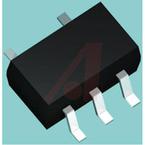
MMBT2222ATT1
General Purpose Transistor
NPN Silicon
These transistors are designed for general purpose amplifier
applications. They are housed in the SOT−416/SC−75 package which
is designed for low power surface mount applications.
Features
• These Devices are Pb−Free, Halogen Free/BFR Free and are RoHS
Compliant
MAXIMUM RATINGS (T
A
= 25°C)
Rating
Symbol Max Unit
Collector−Emitter Voltage V
CEO
40 Vdc
Collector−Base Voltage V
CBO
75 Vdc
Emitter−Base Voltage V
EBO
6.0 Vdc
Collector Current − Continuous I
C
600 mAdc
THERMAL CHARACTERISTICS
Characteristic Symbol Max Unit
Total Device Dissipation (Note 1)
T
A
= 25°C
P
D
150 mW
Thermal Resistance,
Junction−to−Ambient
R
q
JA
833 °C/W
Operating and Storage Junction
Temperature Range
T
J
, T
stg
−55 to +150 °C
Stresses exceeding Maximum Ratings may damage the device. Maximum
Ratings are stress ratings only. Functional operation above the Recommended
Operating Conditions is not implied. Extended exposure to stresses above the
Recommended Operating Conditions may affect device reliability.
1. Device mounted on FR4 glass epoxy printed circuit board using the minimum
recommended footprint.
Device Package Shipping
†
ORDERING INFORMATION
MARKING DIAGRAM
COLLECTOR
3
1
BASE
2
EMITTER
http://onsemi.com
†For information on tape and reel specifications,
including part orientation and tape sizes, please
refer to our Tape and Reel Packaging Specification
Brochure, BRD8011/D.
1P M G
G
1
MMBT2222ATT1G SOT−416
(Pb−Free)
3000 / Tape & Reel
1P = Specific Device Code
M = Date Code
G = Pb−Free Package
(Note: Microdot may be in either location)
CASE 463
SOT−416/SC−75
STYLE 1
3
2
1
Verzeichnis