


Application Report
SLAA409A – June 2009
1
Implementation of a Three-Phase Electronic Watt-Hour
Meter Using the MSP430F471xx
Stephen Underwood, Vincent Chan and Kripasagar Venkat MSP430 Applications
ABSTRACT
This application report describes the implementation of a three phase electronic electricity
meter using the Texas Instruments MSP430F471xx system-on-chip (SOC) processor.
This application report includes the necessary information with regard to metrology
software, hardware and calibration procedures for this single chip implementation. Results
are included at the end, which show performance of this device for three phase using
current transformers as sensors.
1 Introduction
The MSP430F471xx devices belong to the MSP430F4xx family of devices. These devices
find its application in energy measurement and have the necessary architecture to support
it. The MSP430F471xx devices have a powerful 16 MHz CPU with MSP430CPUx
architecture. The analog front-end consists of up to seven analog to digital converters
(ADC) based on a 2
nd
order sigma-delta architecture that supports differential inputs. The
sigma-delta ADCs (SD16) that have a resolution of 16-bits can be configured and grouped
together for simultaneous sampling of voltages and currents on the same trigger. Each
SD16 supports a common mode voltage of up to -1 V and enables all sensors to be
referenced to ground. In addition, it also has an integrated gain stage to support gains up
to 32 for amplification of low-output sensors. A 32-bit x 32-bit HW multiplier on this chip
can be used to further accelerate math intensive operations during energy computation.
The SW supports calculation of various parameters for total three phase and for each
individual phases. The key parameters calculated during energy measurements are: RMS
current and voltage, Active and reactive power, power factor and frequency. The entire
operations take about 1/3
rd
of the processing power and use about a tenth of resources.
The application note has complete metrology source code provided as a zip file.
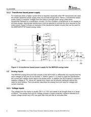
2 Block diagram
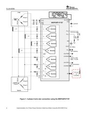
Figure 1 depicts the block diagram that shows the high level interface used for a three-phase
energy meter application. A three-phase four wire star connection to the mains is shown in this
case. Current transformers (CT) are connected to each of the current channels and a simple
voltage divider is used for corresponding voltages. Each CT has an associated burden resistor
that has to be connected at all times to protect the measuring device. The choice of the CT and
the burden resistor is done based on the manufacturer and current range required for energy
measurements. The choice of voltage divider resistors for each voltage channel is selected to
ensure the mains voltage is divided down to adhere to the normal input ranges that are valid for
the MSP430 SD16. Refer to the 4xx user’s guide and specific datasheet for these numbers.
Verzeichnis
- ・ Blockdiagramm on Seite 1 Seite 28
- ・ Anwendungsbereich on Seite 1 Seite 31