

herunterladen
© Semiconductor Components Industries, LLC, 2013
May, 2013 − Rev. 7
1 Publication Order Number:
ADT7463/D
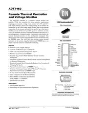
ADT7463
Remote Thermal Controller
and Voltage Monitor
The ADT7463 controller is a complete systems monitor and
multiple PWM fan controller for noise−sensitive applications
requiring active system cooling. It can monitor 12 V, 5 V, and 2.5 V
CPU supply voltages, plus its own supply voltage. It can monitor the
temperature of up to two remote sensor diodes, plus its own internal
temperature. It can measure and control the speed of up to four fans so
that they operate at the lowest possible speed for minimum acoustic
noise. The automatic fan speed control loop optimizes fan speed for a
given temperature. A unique dynamic T
MIN
control mode enables the
system thermals/acoustics to be intelligently managed. The
effectiveness of the system’s thermal solution can be monitored using
the THERM
input. The ADT7463 also provides critical thermal
protection to the system using the bidirectional THERM
pin as an
output to prevent system or component overheating.
Features
• Monitors Up to 5 Supply Voltages
• Controls and Monitors up to 4 Fan Speeds
• 1 On−Chip and 2 Remote Temperature Sensors
• Monitors Up to 6 Processor VID Bits
• Dynamic T
MIN
Control Mode Optimizes System Acoustics
Intelligently
• Automatic Fan Speed Control Mode Controls System Cooling Based
on Measured Temperature
• Enhanced Acoustic Mode Dramatically Reduces User Perception of
Changing Fan Speeds
• Thermal Protection Feature via THERM Output
• Monitors Performance Impact of Intel
®
Pentium
®
4 Processor
Thermal Control Circuit via THERM
Input
• 2−wire and 3−wire Fan Speed Measurement
• Limit Comparison of All Monitored Values
• Meets SMBus 2.0 Electrical Specifications
(Fully SMBus 1.1 Compliant)
• This is a Pb−Free Device
Applications
• Low Acoustic Noise PCs
• Networking and Telecommunications Equipment
http://onsemi.com
See detailed ordering and shipping information in the package
dimensions section on page 49 of this data sheet.
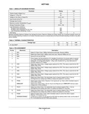
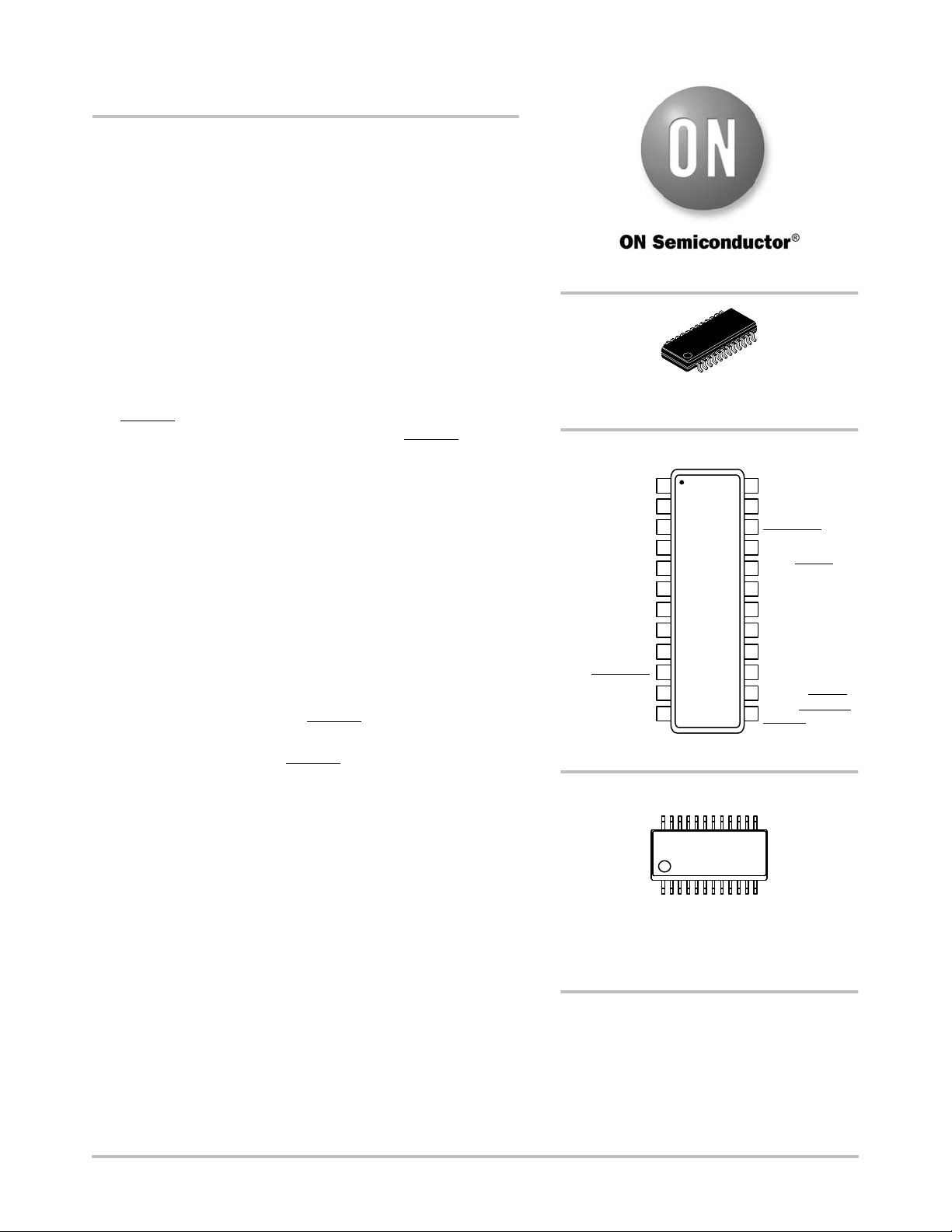
ORDERING INFORMATION
MARKING DIAGRAM
PIN ASSIGNMENT
QSOP24 NB
CASE 492B
ADT7463ARQZ = Specific Device Code
# = Pb−Free Package
YY = Date Code
WW = Work Week
+2.5V
IN
/
SMBALERT
PWM1/XTO
V
CCP
+12V
IN
/VID5
+5V
IN
/THERM
D1+
TACH4/ADDR
SELECT/THERM
VID4
SDA
SCL
GND
V
CC
VID0
VID1
VID2
PWM2/
SMBALERT
24
23
22
21
20
19
18
17
8
7
6
5
4
3
2
1
ADT7463
(Top View)
ADT7463A
RQZ#YYWW
16
9
15
10
14
11
13
12
VID3
TACH3
TACH1
TACH2
D1−
D2+
D2−
PWM3/ADDRESS
ENABLE
Verzeichnis
- ・ Konfiguration des Pinbelegungsdiagramms on Seite 1 Seite 3 Seite 4
- ・ Abmessungen des Paketumrisses on Seite 50
- ・ Paket-Footprint-Pad-Layout on Seite 50
- ・ Teilenummerierungssystem on Seite 1 Seite 49 Seite 50
- ・ Markierungsinformationen on Seite 1 Seite 50
- ・ Blockdiagramm on Seite 2 Seite 26
- ・ Typisches Anwendungsschaltbild on Seite 25
- ・ Beschreibung der Funktionen on Seite 9
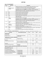
- ・ Technische Daten on Seite 1 Seite 3 Seite 6 Seite 49
- ・ Anwendungsbereich on Seite 1
- ・ Elektrische Spezifikation on Seite 1 Seite 4 Seite 5 Seite 6 Seite 7