herunterladen

© Semiconductor Components Industries, LLC, 2015
October, 2015 − Rev. 6
1 Publication Order Number:
NCN5120/D
NCN5120
Transceiver for KNX
Twisted Pair Networks
Introduction
NCN5120 is a receiver−transmitter IC suitable for use in KNX
twisted pair networks (KNX TP1−256). It supports the connection of
actuators, sensors, microcontrollers, switches or other applications in
a building network.
NCN5120 handles the transmission and reception of data on the bus.
It generates from the unregulated bus voltage stabilized voltages for its
own power needs as well as to power external devices, for example, a
microcontroller.
NCN5120 assures safe coupling to and decoupling from the bus.
Bus monitoring warns the external microcontroller in case of loss of
power so that critical data can be stored in time.
Key Features
• 9600 baud KNX Communication Speed
• Supervision of KNX Bus Voltage
• Supports Bus Current Consumption up to 13 and 26 mA
• Selectable KNX Bus Current (0.5 mA/ms and 1.0 mA/ms)
• High Efficient DC−DC Converters
♦ 3.3 V Fixed
♦ 3.3 V to 21 V Selectable
• Control and Monitoring of Power Regulators
• Linear 20 V Regulator
• Prepared for Sleep Mode
• Buffering of Sent Data Frames (Extended Frames Supported)
• Selectable UART or SPI Interface to Host Controller
• Selectable UART and SPI baud Rate to Host Controller
• Optional CRC on UART to the Host
• Optional Received Frame−end with MARKER Service
• Optional Direct Coupling of RxD and TxD to Host (analog mode)
• Operates with Industry Standard Low Cost 16 MHz Quartz
• Generates Clock of 8 or 16 MHz for External Devices
• Auto Acknowledge (optional)
• Auto Polling (optional)
• Temperature Monitoring
• Operating Temperature Range −25°C to +85°C
• These Devices are Pb−Free and are RoHS Compliant
www.onsemi.com
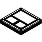
QFN40
MN SUFFIX
CASE 485AU
See detailed ordering and shipping information in the package
dimensions section on page 54 of this data sheet.
ORDERING INFORMATION
A = Assembly Location
WL = Wafer Lot
YY = Year
WW = Work Week
G = Pb−Free Package
MARKING DIAGRAM
401
NCN5120
21245−002
AWLYYWWG
Verzeichnis
- ・ Konfiguration des Pinbelegungsdiagramms on Seite 3
- ・ Abmessungen des Paketumrisses on Seite 55
- ・ Paket-Footprint-Pad-Layout on Seite 55
- ・ Teilenummerierungssystem on Seite 1 Seite 54 Seite 55
- ・ Markierungsinformationen on Seite 1 Seite 55
- ・ Blockdiagramm on Seite 2 Seite 3 Seite 4 Seite 13 Seite 14
- ・ Typisches Anwendungsschaltbild on Seite 13 Seite 14
- ・ Beschreibung der Funktionen on Seite 1 Seite 16 Seite 26
- ・ Technische Daten on Seite 5
- ・ Anwendungsbereich on Seite 13 Seite 14
- ・ Elektrische Spezifikation on Seite 5
- ・ Teilenummernliste on Seite 5


