


herunterladen
© Semiconductor Components Industries, LLC, 2014
October, 2014 − Rev. 6
1 Publication Order Number:
NCN6001/D
NCN6001
Compact Smart Card
Interface IC
The NCN6001 is an integrated circuit dedicated to the smart card
interface applications. The device handles any type of smart card
through a simple and flexible microcontroller interface. On top of that,
thanks to the built−in chip select pin, several couplers can be
connected in parallel.
The device is particularly suited for low cost, low power
applications, with high extended battery life coming from extremely
low quiescent current.
Features
• 100% Compatible with ISO 7816−3, EMV and GIE−CB Standards
• Fully GSM Compliant
• Wide Battery Supply Voltage Range: 2.7 < V
CC
< 5.5 V
• Programmable CRD_VCC Supply Handles 1.8 V, 3.0 V or 5.0 V
Card Operation
• Programmable Rise and Fall Card Clock Slopes
• Programmable Card Clock Divider
• Built−in Chip Select Logic Allows Parallel Coupling Operation
• ESD Protection on Card Pins (8.0 kV, Human Body Model)
• Supports up to 40 MHz Input Clock
• Built−in Programmable CRD_CLK Stop Function Handles Run or
Low State
• Programmable CRD_CLK Slopes to Cope with Wide Operating
Frequency Range
• Fast CRD_VCC Turn−on and Turn−off Sequence
• These are Pb−Free Devices
Typical Applications
• E−Commerce Interface
• Automatic Teller Machine (ATM) Smart Card
• Point of Sales (POS) System
• Pay TV System
www.onsemi.com
TSSOP−20
DTB SUFFIX
CASE 948E
MARKING DIAGRAM
20
1
NCN
6001
ALYWG
G
1
A = Assembly Location
L = Wafer Lot
Y = Year
W = Work Week
G = Pb−Free Package
(Note: Microdot may be in either location)
See detailed ordering and shipping information in the package
dimensions section on page 32 of this data sheet.
ORDERING INFORMATION
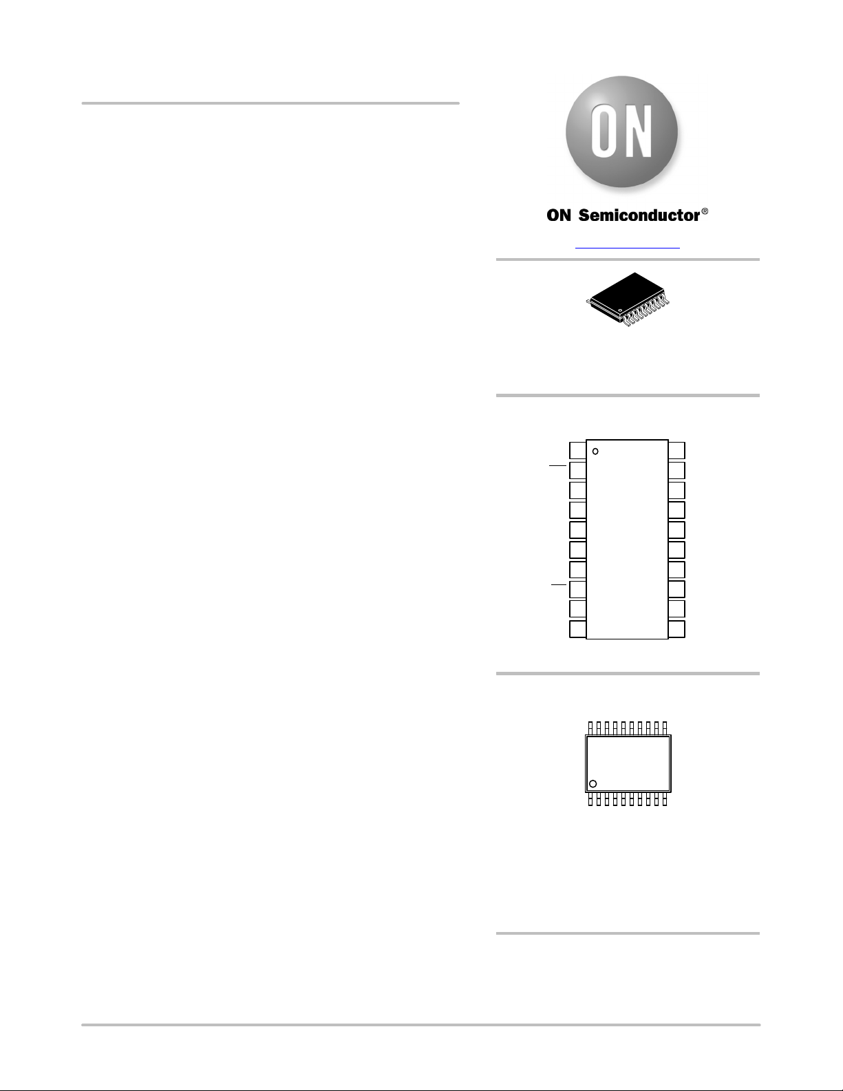
PIN CONNECTIONS
1
2
3
4
5
6
7
8
20
19
18
16
15
14
13
(Top View)
CLK_SPI
I/O
INT
CLK_IN
MOSI
EN_RPU
MISO
CS
Lout_H
GND
CRD_VCC
CRD_CLK
CRD_IO
9
10 11
12
17
V
CC
Lout_L PWR_GND
CRD_RST
CRD_DET
C8/S1
C4/S0
Verzeichnis
- ・ Konfiguration des Pinbelegungsdiagramms on Seite 1 Seite 3 Seite 4 Seite 5
- ・ Abmessungen des Paketumrisses on Seite 33
- ・ Paket-Footprint-Pad-Layout on Seite 33
- ・ Teilenummerierungssystem on Seite 1 Seite 32 Seite 33
- ・ Markierungsinformationen on Seite 1 Seite 33
- ・ Blockdiagramm on Seite 2 Seite 28
- ・ Typisches Anwendungsschaltbild on Seite 1 Seite 2
- ・ Technische Daten on Seite 32
- ・ Anwendungsbereich on Seite 1
- ・ Elektrische Spezifikation on Seite 7
- ・ Teilenummernliste on Seite 6