

herunterladen
Semiconductor Components Industries, LLC, 2002
March, 2002 – Rev. 5
1 Publication Order Number:
NCP100/D
NCP100
Sub 1.0 V Precision
Adjustable Shunt Regulator
The NCP100 is a precision low voltage shunt regulator that is
programmable over a voltage range of 0.9 V to 6.0 V. This device
features a guaranteed reference accuracy of ±1.7% at 25°C and ±2.6%
over the entire temperature range of –40°C to 85°C. The NCP100
exhibits a sharp low current turn–on characteristic with a low dynamic
impedance of 0.20 over an operating current range of 100 A to
20 mA. These characteristics make this device an ideal replacement
for zener diodes in numerous application circuits that require a precise
low voltage reference. When combined with an optocoupler, the
NCP100 can be used as an error amplifier for controlling the feedback
loop in isolated low output voltage (2.3 V) switching power supplies.
This device is available in an economical space saving TSOP–5
package.
Features
• Programmable Output Voltage Range of 0.9 V to 6.0 V
• Voltage Reference Tolerance of ±1.7%
• Sharp Low Current Turn–ON Characteristic
• Low Dynamic Output Impedance of 0.2 from 100 A to 20 mA
• Wide Operating Current Range of 80 A to 20 mA
• Space Saving TSOP–5 Package
Applications
• Reference for Single Cell Alkaline, NiCD and NiMH Applications
• Low Output Voltage (2.3 V) Switching Power Supply Error Amp
• Battery Powered Consumer Products
• Portable Test Equipment and Instrumentation
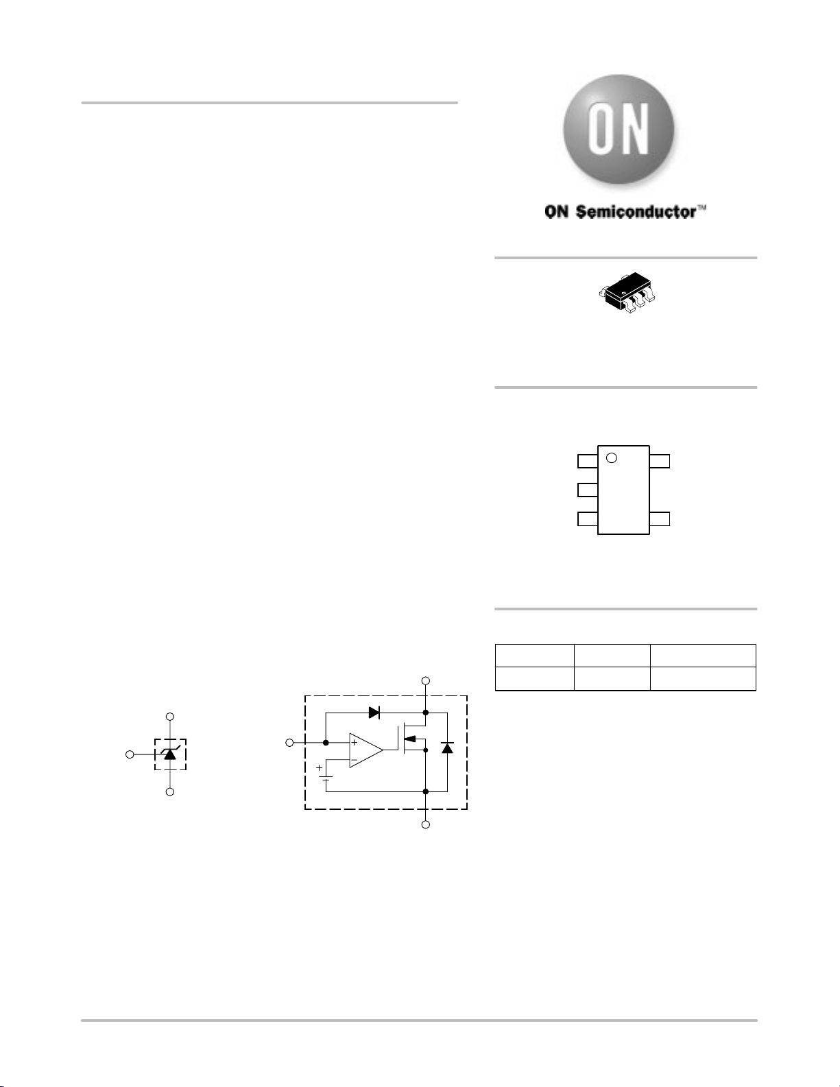
Cathode (K)
Reference
(R)
Anode (A)
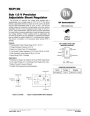
Figure 1. Symbol Figure 2. Representative Block Diagram
Cathode (K)
Reference
(R)
Anode (A)
0.7 V
http://onsemi.com
TSOP–5
SN SUFFIX
CASE 483
1
5
PIN CONNECTIONS AND
MARKING DIAGRAM
1
3
Reference
NC
2
Anode
Cathode
4
Anode
5
RAByyww
(Top View)
Device Package Shipping
ORDERING INFORMATION
NCP100SNT1 TSOP–5 3000 Units / 7″ Reel
YY = Year
WW = Work Week
Verzeichnis
- ・ Konfiguration des Pinbelegungsdiagramms on Seite 1
- ・ Abmessungen des Paketumrisses on Seite 10
- ・ Teilenummerierungssystem on Seite 1 Seite 12
- ・ Markierungsinformationen on Seite 1
- ・ Blockdiagramm on Seite 1
- ・ Typisches Anwendungsschaltbild on Seite 6
- ・ Anwendungsbereich on Seite 1 Seite 6 Seite 9
- ・ Elektrische Spezifikation on Seite 2