


herunterladen
Semiconductor Components Industries, LLC, 2002
December, 2002 - Rev. 2
1 Publication Order Number:
NTGS3446/D
NTGS3446T1
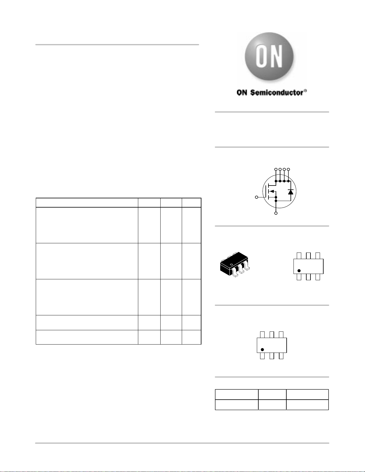
Power MOSFET
5.1 Amps, 20 Volts
N-Channel TSOP-6
Features
• Ultra Low R
DS(on)
• Higher Efficiency Extending Battery Life
• Logic Level Gate Drive
• Diode Exhibits High Speed, Soft Recovery
• Avalanche Energy Specified
• I
DSS
Specified at Elevated Temperature
Applications
• Power Management in portable and battery-powered products, i.e.
computers, printers, PCMCIA cards, cellular and cordless
• Lithium Ion Battery Applications
• Notebook PC
MAXIMUM RATINGS (T
C
= 25°C unless otherwise noted)
Rating
Symbol Value Unit
Thermal Resistance
Junction-to-Ambient (Note 1)
Total Power Dissipation @ T
A
= 25°C
Drain Current
- Continuous @ T
A
= 25°C
- Pulsed Drain Current (t
p
10 s)
R
JA
P
d
I
D
I
DM
244
0.5
2.5
10
°C/W
Watts
Amps
Amps
Thermal Resistance
Junction-to-Ambient (Note 2)
Total Power Dissipation @ T
A
= 25°C
Drain Current
- Continuous @ T
A
= 25°C
- Pulsed Drain Current (t
p
10 s)
R
JA
P
d
I
D
I
DM
128
1.0
3.6
14
°C/W
Watts
Amps
Amps
Thermal Resistance
Junction-to-Ambient (Note 3)
Total Power Dissipation @ T
A
= 25°C
Drain Current
- Continuous @ T
A
= 25°C
- Pulsed Drain Current (t
p
10 s)
R
JA
P
d
I
D
I
DM
62.5
2.0
5.1
2.0
°C/W
Watts
Amps
Amps
Operating and Storage Temperature Range T
J
, T
stg
- 55 to
150
°C
Maximum Lead Temperature for Soldering
Purposes for 10 seconds
T
L
260 °C
1. Minimum FR-4 or G-10PCB, operating to steady state.
2. Mounted onto a 2” square FR- 4 board (1” sq. 2 oz. cu. 0.06” thick
single-sided), operating to steady state.
3. Mounted onto a 2” square FR- 4 board (1” sq. 2 oz. cu. 0.06” thick
single-sided), t < 5.0 seconds.
1256
3
5.1 AMPERES
20 VOLTS
R
DS(on)
= 45 m
Device Package Shipping
ORDERING INFORMATION
NTGS3446T1 TSOP-6 3000 Tape & Reel
N-Channel
TSOP-6
CASE 318G
STYLE 1
W
MARKING
DIAGRAM
446
446 = Device Code
W = Work Week
PIN ASSIGNMENT
3
Gate
1
Drain
Source
4
6
5
4
1
2
3
2
Drain
Drain
5
Drain
6
4
Drain
Gate
Source
http://onsemi.com
Verzeichnis