


herunterladen
1
5
8
11
9
4
2
©
1991 Burr-Brown Corporation AB-025 Printed in U.S.A. June, 1997
®
Ever-increasing demands are being placed on instrumenta-
tion amplifier (IA) performance. When standard IAs can not
deliver the required performance, consider this enhanced
version. Dramatic performance improvements can be
achieved by operating the input amplifiers of a classical
three-op-amp IA from common-mode driven sub-regulated
power supplies.
Instrumentation amplifiers are designed to amplify low-
level differential signals while rejecting unwanted common-
mode signals. One of the most important specifications is
common-mode rejection (CMR)—the ability to reject com-
mon mode signals. AC CMR is especially important since
the common-mode signals are inevitably dynamic—com-
monly ranging from 60Hz power-line interference to switch-
ing-power-supply noise at tens to hundreds of kHz. With
common-mode driven sub-regulated supplies, both the AC
and DC CMR of the IA can be dramatically improved.
Improved AC and DC power supply noise rejection is an
added bonus.
At the high gains often required, input offset voltage drift
can also be a critical specification. In some applications, the
low input offset voltage drift of chopper stabilized op amps
might provide the best solution. But, since many of these
chopper stabilized op amps are built using low voltage
CMOS processes, they can not be operated on standard
±15V power supplies. Operating the chopper stabilized op
amps from common-mode-driven, sub-regulated ±5V sup-
plies allows them to be used without restriction in ±15V
systems.
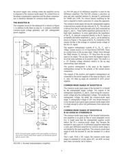
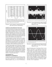
THE THREE OP AMP IA
To understand how the technique works, first consider the
operation of the three op amp IA shown in Figure 1A. The
design consists of an input gain stage driving a difference
amplifier.
The difference amplifier consists of op amp A
3
and ratio
matched resistors R
1
through R
4
. If the resistor ratios R
2
/R
1
exactly match R
4
/R
3
the difference amplifier will amplify
differential signals by a gain of R
2
/R
1
while rejecting com-
mon-mode signals. The CMR of the difference amplifier
will almost certainly be limited by resistor mismatch when
a high-performance op amp is used for A
3
. A unity-gain
difference amplifier requires a difficult 0.01% resistor match
for CMR of 86dB.
Since the slightest input source impedance mismatch would
degrade the resistor matching of the difference amplifier, a
differential input, differential output gain-stage (A
1
, A
2
,
R
FB1
, R
FB2
, and R
G
) is used ahead of the difference amplifier.
The low output-impedance of the of the gain stage preserves
difference amplifier resistor matching and maintains the
CMR of the difference amplifier. The input amplifiers also
provide high input impedance and additional gain.
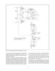
When designing a high CMR instrumentation amplifier, it is
important to use a differential input, differential output
amplifier using a single gain-set resistor (see Figure 1A). In
the Figure 1A circuit, CMR is independent of resistor
matching. Resistor mismatches degrade CMR in the two
gain-set-resistor differential in/out amplifier (see Figure 1B).
To understand why CMR is independent of resistor match-
ing in the single gain-set resistor amplifier, consider the
Figure 1A circuit. With a common-mode input signal, and
no differential input signal, the voltage between V
N
and V
P
does not change. Therefore the voltage across R
G
remains
constant and, since no current flows in the op amp inputs,
there is no current change in R
FB1
or R
FB2
, and the differential
output voltage, V
1
-V
2
, does not change. Ideally then, with a
perfect difference amplifier, the common-mode gain is zero
and the CMRR is ∞.
R
2
A
3
A
1
A
2
R
1
R
FB1
R
4
R
3
R
FB2
R
G
V
N
V
P
V
1
V
2
Difference Amplifier
V
O
Mismatches in gain-set resistors R
FB1
and R
FB2
do not degrade IA
CMR.
GAIN = (1 + [R
FB1
+ R
FB2
]/R
G
) (R
2
/R
1
)
If R
FB1
= R
FB2
= R
FB
,
GAIN = (1 + [2 • R
FB
]/R
G
) (R
2
/R
1
)
FIGURE 1A. The Three Op-Amp Instrumentation Ampli-
fier.
BOOST INSTRUMENT AMP CMR
WITH COMMON-MODE DRIVEN SUPPLIES
By R. Mark Stitt
SBOA014