
herunterladen
Cell Phone Base Station Protection
Circuit Protection Application Note
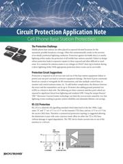
The Protection Challenge
Mobile phone base stations are oen placed in exposed elevated locations for the
maximum possible broadcast coverage. Oen this unintentionally results in the erection
of an ideally positioned lightning conductor. Protection against inevitable direct or nearby
lightning strikes makes the protection of all mobile base stations essential. Failure to design
robust protection leads to expensive repairs in these exposed and oen dicult to reach
areas. It is common for antenna masts to see voltages of 250 kV from top to bottom during
a direct lightning strike! With appropriate protection these events can be survivable.
Protection Circuit Suggestions
Protection is required on all services into and out of the base station equipment; failure to
protect just one port can lead to extensive equipment damage. e kind of ports commonly
found are coaxial or waveguide for RF transmission, and also multiple control lines, to
monitor and control antenna status, etc. To add further complication, the distance between
the tower and the transmitters can be up to 30 meters also adding ground potential rise
(GPR) as a threat to deal with. e following are three common interface ports which are
exposed to signicant threat from lightning and resultant GPR. Using the unique Bourns®
TBU™ Electronic Current Limiter technology can limit the overcurrents caused by very fast
lightning events resulting in greater system reliability and ultimately lifetime cost savings.
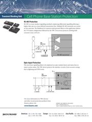
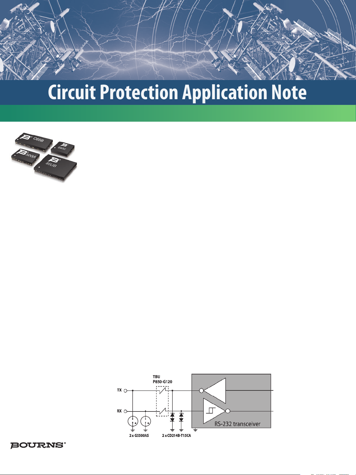
RS-232 Protection
RS-232 is a relatively old signalling standard which dates back to the late 1960s. Logic
states “0” and “1” are ±5 V to ±12 V on the transmit (TX) lines, and are ±3 V to ±15 V for
the receive (RX) lines. erefore a symmetrical protection topology is suggested allowing
the datastream to pass with some common mode oset on either the TX or RX lines
without damage or signal degradation. e TBU device limits currents into or out of the
interface to ±120 mA.