

herunterladen

®
©
1999 Burr-Brown Corporation AB-147A Printed in U.S.A. July, 1999
The information provided herein is believed to be reliable; however, BURR-BROWN assumes no responsibility for inaccuracies or omissions. BURR-BROWN assumes
no responsibility for the use of this information, and all use of such information shall be entirely at the user’s own risk. Prices and specifications are subject to change
without notice. No patent rights or licenses to any of the circuits described herein are implied or granted to any third party. BURR-BROWN does not authorize or warrant
any BURR-BROWN product for use in life support devices and/or systems.
CONTROL PORT AND RESET
OPERATION FOR BURR-BROWN
AUDIO CONVERTERS AND CODECS
By Robert Martin and Satoshi Urano
PURPOSE
This application bulletin provides operational details of the
serial control port and reset functions for Burr-Brown digital
audio data converters and CODECs. Specifically, this infor-
mation applies to the PCM1716, PCM1717, PCM1719,
PCM1720, PCM1723, PCM1727, PCM3000-series
CODECs, and the PCM1800 A/D converter.
INTRODUCTION
Many of Burr-Brown’s digital audio products include a
three-wire serial control port for accessing special on-chip
functions, such as digital attenuation, data format selection,
soft mute, and output phase reversal.
For some devices, the control port is active only when
Software mode is selected. The control port is inactive when
these devices are operated in Hardware mode. For other
devices, the control port is the only method available for
changing the power-up default state. The operation of the
serial control port is detailed in the next two sections. The
last three sections of this document describe the proper reset
of these devices when operated in Software and Hardware
modes.
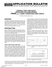
SERIAL CONTROL PORT OPERATION
Figure 1 shows a simplified block diagram of the serial
control port. The port includes three input signals, named
MC, ML, and MD. MC is the serial shift clock, used to clock
data into the shift register inside the serial-to-parallel con-
verter. MD is the serial control data, which is clocked into
the serial-to-parallel converter one bit for every rising edge
of the MC clock. Data is presented to the MD as a 16-bit
serial word. ML is used to latch 16-bit data at the parallel
output of the serial-to-parallel converter. A simplified tim-
ing diagram illustrating the control port operation is shown
in Figure 2. A detailed timing diagram is presented in Figure 3.
TM
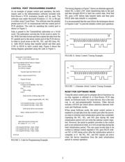
As shown in Figure 3, in order to write 16 bits of data to the
control port, the rising edge of ML must occur after the least
significant bit (LSB) of MD has been clocked into the serial
control port by MC. The timing parameter t
MLH
defines the
minimum time delay between MC rising edge (when data on
MD is clocked into the serial-to parallel converter) and the
low-to-high transition of ML, which latches the 16 bits of
control data into the control port Take a moment to study
the remaining timing parameters listed in Figure 3, with
special attention given to the minimum setup and hold time
requirements.
Data can be written to the serial control port in either a
continuous or burst (one-shot) fashion. Figure 4 shows
examples for both techniques. Notice that there are two
cases for ML for each example. You may use either case in
your application.
To Internal
Register
Latch
Data
Serial-to-Parallel
Converter
MD
MC
ML
FIGURE 1. Simplified Block Diagram of Serial Control
Section.
B15 B14 B2 B1 B0
ML
MC
MD
FIGURE 2. Simplified Control Timing.
SBAA032