

herunterladen

© 2009 Microchip Technology Inc. DS01268A-page 1
AN1268
INTRODUCTION
This application note is an addendum to the information
in the previous capacitive touch sensing application
notes, found on Microchip’s web site. It builds
specifically on AN1101, “Introduction to Capacitive
Sensing”. This application note focuses on how to use
either an SR latch enabled part, or our new family of
parts with a dedicated Cap Sense Module (CSM) to
measure changes in capacitance using a period
measurement instead of frequency measurement.
Using this new method provides higher resolution than
the frequency measurement and permits faster
scanning.
THEORY OF OPERATION
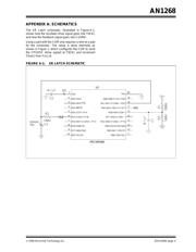
The basic principle is that a relaxation oscillator will be
created with the microcontroller and the sensing pad’s
capacitance. This oscillation should be on the order of
200 to 500 kHz (using the CSM module, no work is
required but to have a sensor pad, and the oscillations
will be in this range when using the high power setting;
for the SR latch devices, a 100 kOhm feedback resistor
will typically put the sensors in that region - Figure A-1).
When a user’s finger touches the sensor, it will reduce
the relaxation oscillator frequency and increase the
period. This increase in period will be detected.
Configuring the Hardware
The period will not be measured as a value, such as
8µsec but, instead, will be a count in Timer1
representing period through some scaling factors. This
method will use Timer0 and Timer1, but now the inputs
to Timer0 and Timer1 are reversed. The input of Timer1
will be F
OSC/4, or a multiple, and the input of Timer0 will
be the relaxation oscillator drive signal.
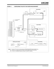
Figure 1 on page 3 shows how to configure the
PIC16F727 family of devices to perform this period
measurement using the Cap Sense Module (CSM).
Obtaining a Reading
At the beginning of a reading, Timer1 is cleared, and
Timer0 may be cleared or preloaded with a fixed value.
Preloading a value, other than 0, will make the
sampling time shorter. On the interrupt of Timer0, the
value of Timer1 is the reading. The internal oscillator of
the device will run at 4, 8, or 16 MHz, orders of
magnitude faster than the relaxation oscillator. The
Timer1 result is a ratio of the frequency of the internal
oscillator over the frequency of the relaxation oscillator,
and this is multiplied by the number of periods
measured (how many times Timer0 counted – 255
periods if starting from 0), as shown in Equation 1
below:
EQUATION 1:
The Timer1 value is a representation of the period of
the relaxation oscillator. This value will be watched for
an increase, signaling touch.
SOFTWARE DECODING
The software decoding for the period measurement is
identical to the frequency measurement methods,
except now the reading goes up for a touch, instead of
down. Previously, as frequency decreased, the same
decrease was seen in the reading.
Also, the period measurement is linear only for small
shifts, less than 5-10%. A percentage can still be
computed from the value, and is still useful, but for
large shifts, since the period is 1/f, it increases
exponentially. If you have a large shift, then the signal
shift will be extremely large, allowing for plenty of shift
in the data to work with.
Author: Thomas Perme
Microchip Technology Inc.
reading = (FOSC/4)/(F
RELAXOSC
)
•
N
mTouch™ Capacitive Sensing Using Period Method
Verzeichnis
- ・ Blockdiagramm on Seite 5
- ・ Anwendungsbereich on Seite 2